Connector assembly with gripping sleeve

Active Publication Date: 2009-06-09
AMPHENOL CORP
View PDF43 Cites 162 Cited by
  • Summary
  • Abstract
  • Description
  • Claims
  • Application Information

AI Technical Summary

Benefits of technology

[0006]Accordingly, it is an aspect of the invention to provide a connector assembly with a connec

Problems solved by technology

A loose connection can fail to provide the positive contact needed for continuity between the cable and the device, the other connector, or the other cable.
Also, a loose connection can come apart accidentally disrupting the connection to the device, the other connector, or the other cable.
A loose connection can also cause signal leakage and degraded performance.
Furthermore, connector assemblies are often assembled under conditions in

Method used


Image

  • Connector assembly with gripping sleeve
  • Connector assembly with gripping sleeve
  • Connector assembly with gripping sleeve

Examples


Embodiment Construction

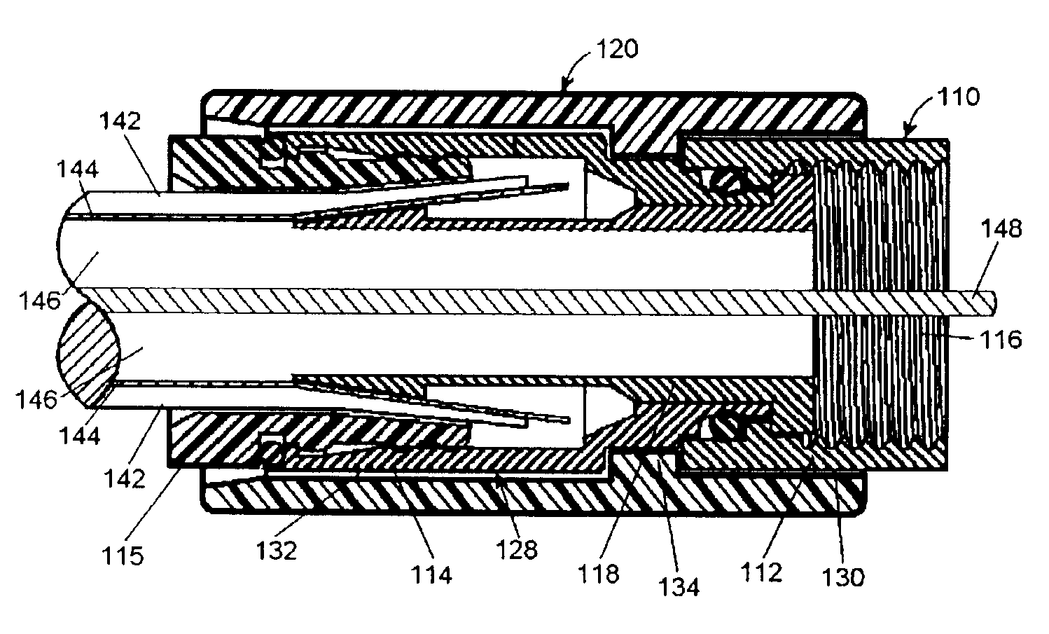
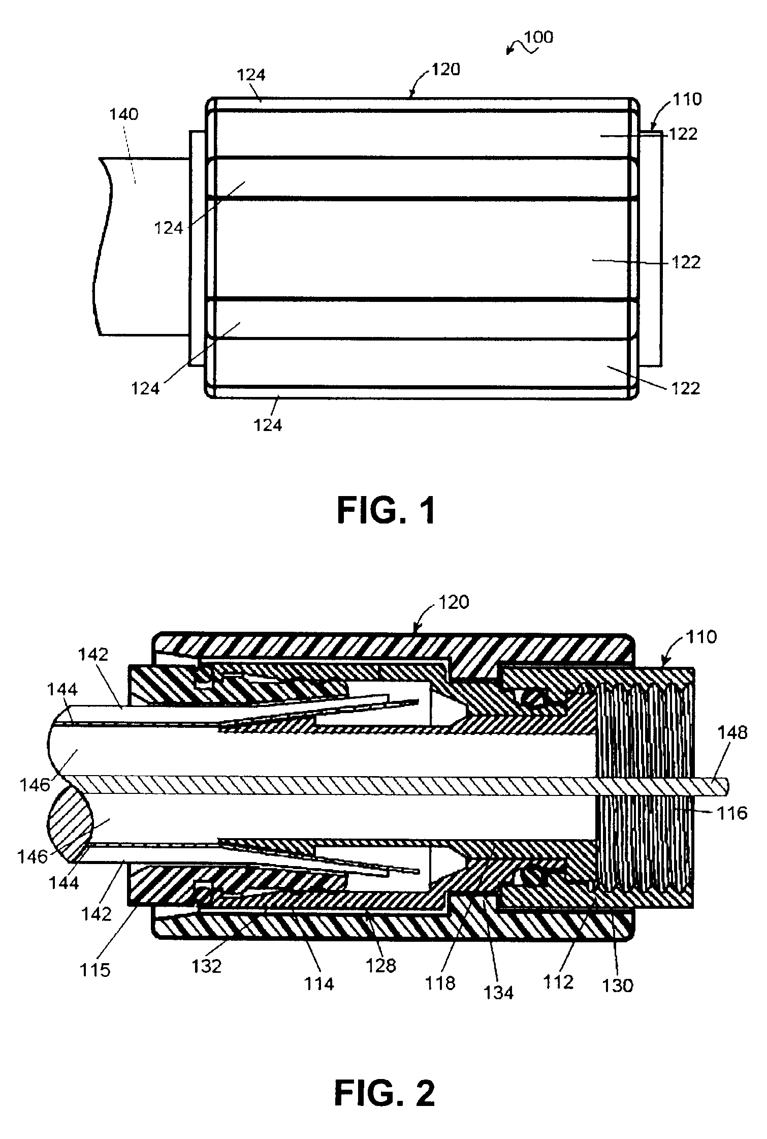
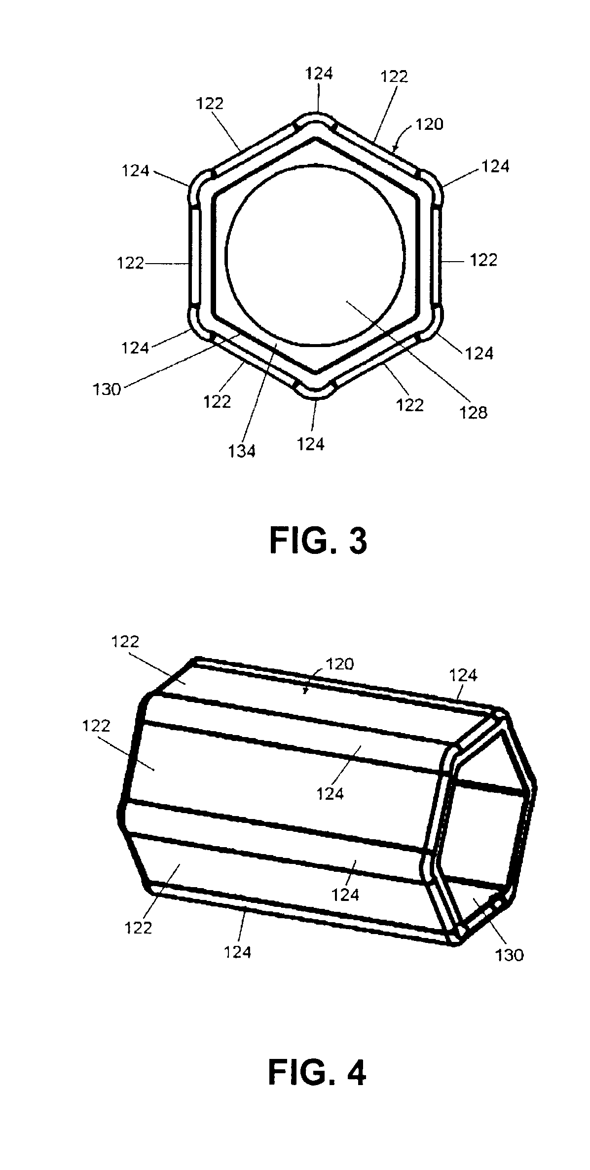
[0025]Referring to FIGS. 1-13, the present invention relates to a connector assembly 100 and a method of manufacturing a connector assembly 100 with a sleeve 120 that ensnares a portion of a connector 110 and provides improved gripping. The sleeve 120 is not easily removed from the connector 110 for safety reasons.

[0026]Referring to FIG. 1, the connector assembly 100 includes, at least, the connector 110 and the sleeve 120. The connector 110 terminates a cable 140 and connects to a mating connector, device, or cable. The connector 110 can be an electrical connector, an optical connector, a fluid connector, a pneumatic connector, a hydraulic connector, or some other type of connector. To simplify and facilitate the description of the invention, the connector 110 will be described as an electrical connector, and in particular, an F connector used with coaxial cables. However, the invention is not limited to only embodiments with an electrical connector.

[0027]The sleeve 120 facilitates...


PUM


Abstract

A connector assembly includes an electrical connector and a sleeve. The electrical connector has opposite first and second ends. The first end is rotatable with respect to the second end and configured to couple to a mating connector. The second end is configured to terminate a cable. The sleeve has an outer gripping surface, and an inner bore for receiving the electrical connector such that the sleeve and the first end of the connector are rotatable together.

Description

CROSS-REFERENCE TO RELATED APPLICATION[0001]This application may relate to commonly assigned, co-pending U.S. patent application Ser. No. 12 / 003,108, entitled “Connector Assembly with Gripping Sleeve”, filed concurrently herewith, the subject matter of which is herein incorporated by reference.FIELD OF THE INVENTION[0002]The present invention relates to connector assemblies with a sleeve. In particular, the present invention relates to electrical connector assemblies with a sleeve to facilitate gripping and mating of a connector to its counterpart connector.BACKGROUND OF THE INVENTION[0003]Connector assemblies are often used to terminate a cable and adapt the cable for attachment to a device, another connector, or another cable. The connector assembly often includes a body with a rotating nut portion with internal threads. The nut portion rotates with respect to the body so that the internal threads of the nut can engage corresponding threads of the device, the other connector, or t...

Claims


Application Information

Patent Timeline
IPC IPC(8): H01R9/05
CPCH01R9/0518H01R24/40H01R43/26H01R2103/00
Inventor PAGLIA, RICHARDCHEN, WEIXINGGU, MINGHUA
Owner AMPHENOL CORP
Why Eureka
Try Eureka