Rotary input apparatus

a technology of input apparatus and input shaft, which is applied in the direction of mechanical control devices, process and machine control, instruments, etc., can solve the problems of non-operation of equipment and increasing the operational burden of the operator

Inactive Publication Date: 2009-06-09
NISSAN MOTOR CO LTD
View PDF16 Cites 78 Cited by
  • Summary
  • Abstract
  • Description
  • Claims
  • Application Information

AI Technical Summary

Benefits of technology

[0006]It is, hence, an object of the present invention to provide a rotary input apparatus and a method applicable to the rotary input apparatus which can prevent the operator from erroneously operating the switch and can be compatible between an erroneous operation prevention function and a favorable operability assurance without impeding the operability assurance without impeding the operability under the situation under which the erroneous operation is not easy to occur by assuring the switch operation itself under the situation under which the erroneous operation is easy to occur when the switch is operated.

Problems solved by technology

Therefore, an operator often erroneously recognizes that this non-operation of the equipment is caused by a failure of the equipment itself.
Consequently, such an action as a long time notice or gazing on a display or re-operation of the switch is taken and there is a possibility of giving a further operational burden on the operator.

Method used


Image

  • Rotary input apparatus
  • Rotary input apparatus
  • Rotary input apparatus

Examples


first embodiment

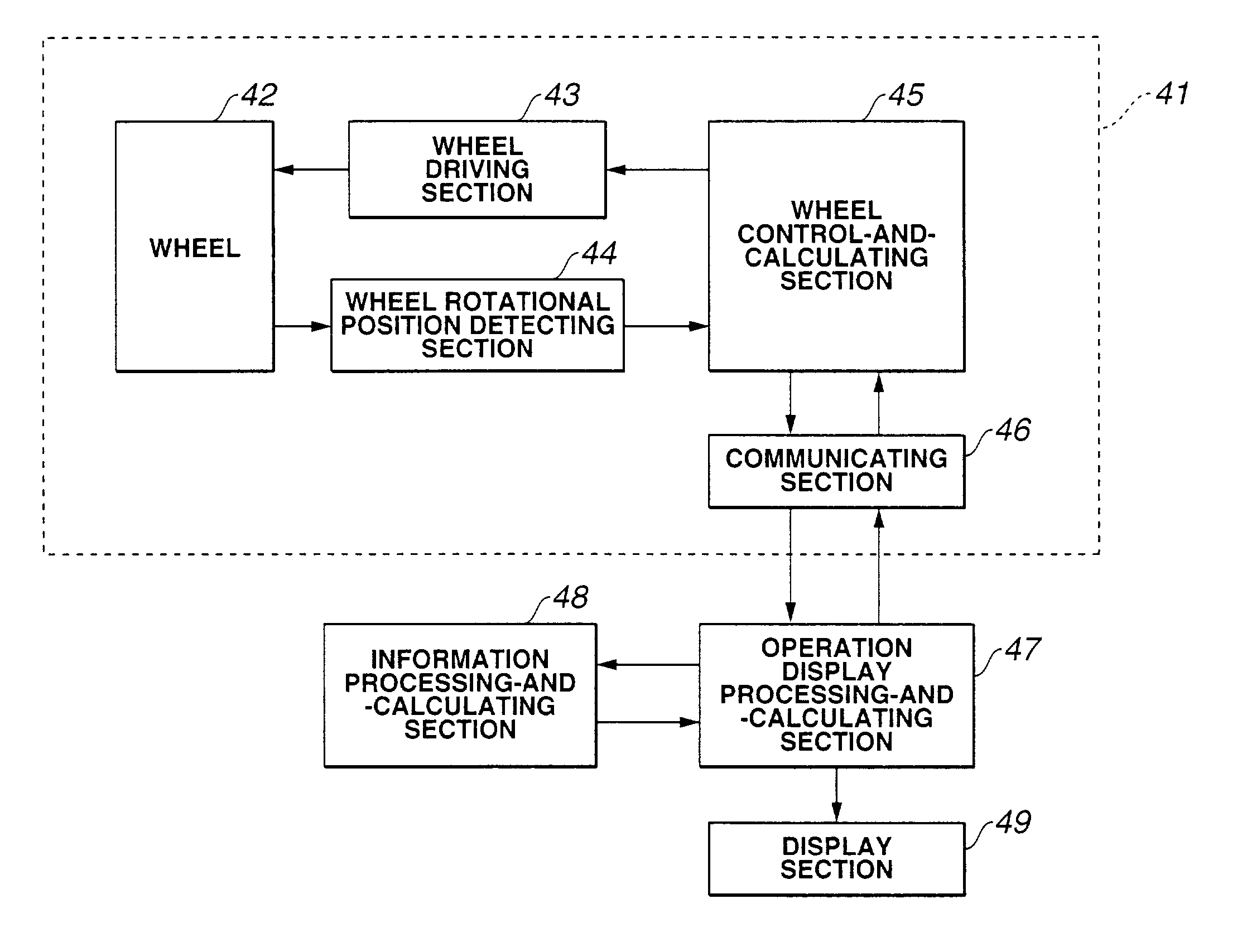
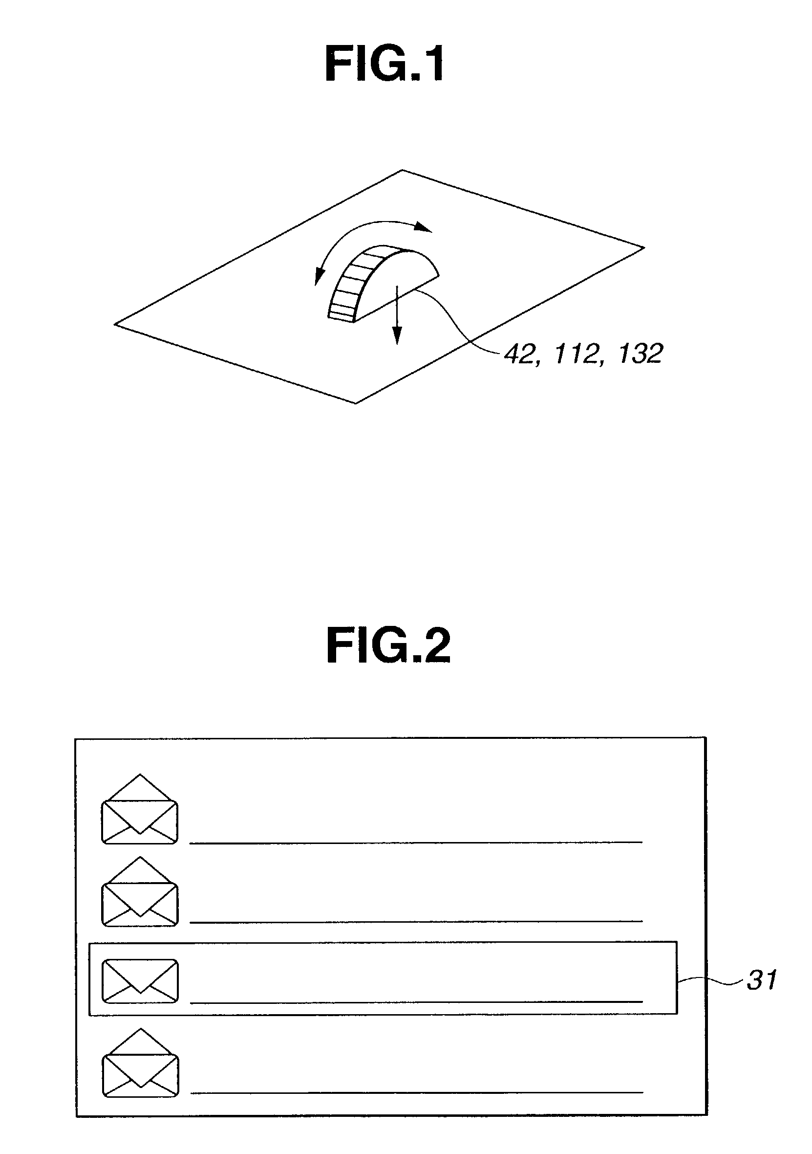
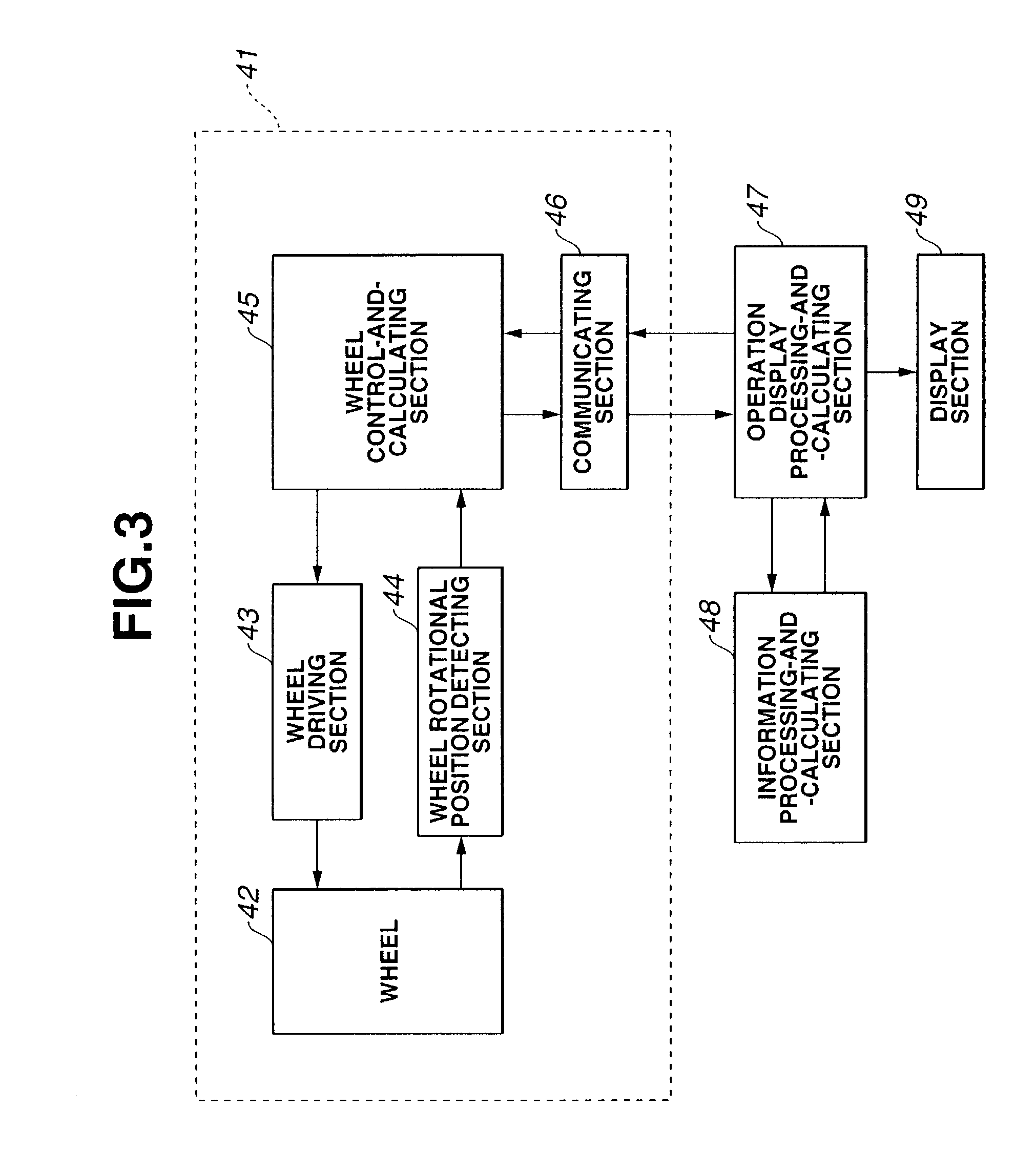
[0024]In the first embodiment, with an operational intensity of a wheel which constitutes an operational end (a kind of rotary switch and also called a jog dial) by an operator and a vibration developed on a surrounding of the operational end taken into consideration, a situation under which an erroneous operation is easy to occur is detected on the basis of a signal of a rotational quantity (or rotational displacement) detection sensor on the operational end. By controlling a reaction force pattern (a resistance force against an operational force developed on the operational end) which is made correspondent to each selection item on a menu selection image screen displayed on a display (display section), the rotary input apparatus in this embodiment prevents an operation mistake (the erroneous operation) by the operator. That is to say, the rotary input apparatus includes wheel 42 whose outer appearance is shown in FIG. 1. For wheel 42, a reversible rotational operation in a rotatio...

second embodiment

[0053]Operational input device 111 in the second embodiment shown in FIG. 10 includes: wheel 112 which constitutes the operational end (refer to the wheel shown in FIG. 1); a wheel driving section 113 which develops the torque in the rotational direction of wheel 112; a wheel rotational position detecting section 114 that detects the rotational angle of wheel 112 and an occurrence of the push operation on wheel 112; a wheel push-down suppressing section 1101 which locks and unlocks the push operation on wheel 112; wheel control-and-calculating section 115; and communicating section 116.

[0054]Wheel control-and-calculating section 115 digitalizes the position detection signal outputted from wheel rotational position detecting section 114 to convert the position detection signal into a wheel position information. This wheel position information is first-order differentiated to calculate the rotational angular velocity of wheel 112 and is second-order differentiated to calculate the rot...


PUM


Abstract

In a rotary input apparatus, an operational end enabled to be rotationally operated is provided, an operational input device detects a rotational displacement of the operational end to move a pointer displayed on a display thereof to perform a selection operation of any one of various kinds of selection items displayed on the display and a driving force generating section generates and transmits a driving force to the operational end in accordance with a reaction force pattern when the operational end is rotationally operated, the operational input device setting the reaction force pattern against the rotational displacement of the operational end and varying the reaction force pattern on the basis of an input signal from at least one of an internal of and an external to the operational input device when the operational end is rotationally operated.

Description

BACKGROUND OF THE INVENTION[0001]1. Field of the Invention[0002]The present invention relates to a rotary input apparatus, for example, mounted on an automotive vehicle and which carries out various operational inputs and, particularly, relates to a technique of preventing an erroneous operation for the rotary input apparatus.[0003]2. Description of the Related Art[0004]A previously proposed on-vehicle operational switch in which an erroneous operation preventing countermeasure is carried out is exemplified by a Japanese Patent Application First Publication No. 2000-100272 published on Apr. 7, 2000. In the previously proposed on-vehicle operational switch, such a state of a large acceleration that a posture of an vehicular occupant tends to become unstable is determined according to various sensor information and, even if the switch operation is carried out during the large acceleration state described above, a switch signal indicating the switch operation is not outputted to a corr...

Claims


Application Information

Patent Timeline
Patent Type & Authority Patents(United States)
IPC IPC(8): G06F3/033G06F3/01G09G5/00G05G5/03G06F3/00G06F3/02G06F3/023G06F3/0362H01H25/06
CPCG06F3/016G06F3/0362G06F2203/014
Inventor SUNDA, TAKASHIMITAMURA, TAKESHI
Owner NISSAN MOTOR CO LTD
Why Eureka
Try Eureka