Vehicle control device
a technology for controlling devices and vehicles, applied in mechanical devices, external condition input parameters, transportation and packaging, etc., can solve problems such as troublesome operation
- Summary
- Abstract
- Description
- Claims
- Application Information
AI Technical Summary
Benefits of technology
Problems solved by technology
Method used
Image
Examples
first embodiment
1. First Embodiment
[0025]
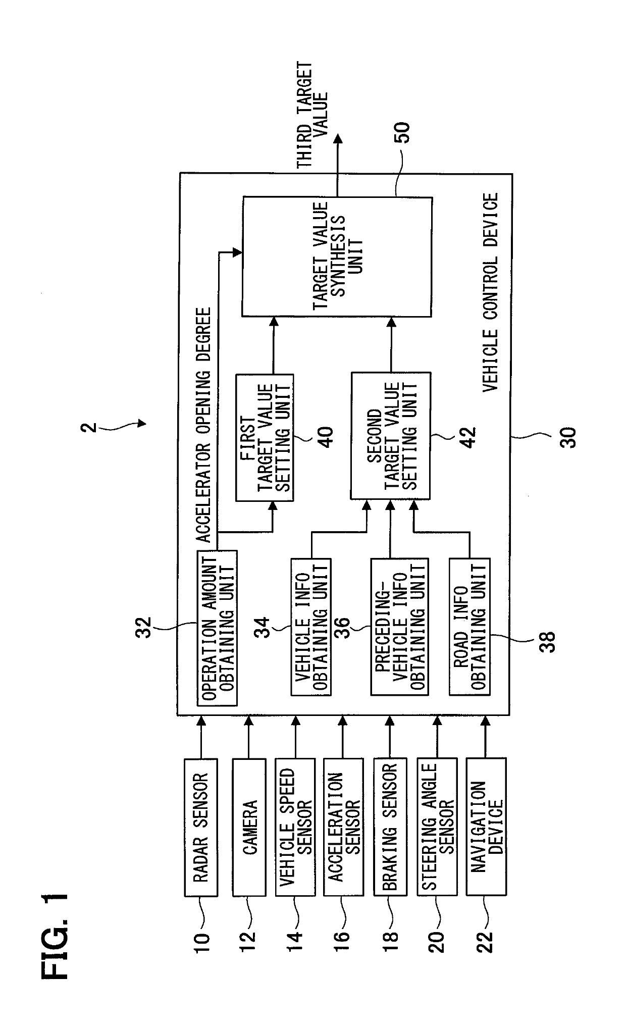
[0026]A vehicle control system 2 shown in FIG. 1 is mounted to a vehicle and controls traveling of the vehicle. The vehicle control system 2 mainly includes various sensors and devices to detect an amount of driver's driving operation, traveling conditions of the subject vehicle, traveling conditions of a preceding vehicle ahead of the subject vehicle, and conditions of the subject vehicle traveling road and the like, and a vehicle control device 30.
[0027]The sensors and devices the vehicle control system 2 is equipped with include a radar sensor 10, a camera 12, a vehicle speed sensor 14, an acceleration sensor 16, a braking sensor 18, a steering angle sensor 20, and a navigation device 22.
[0028]The radar sensor 10 scans, by emitting laser beams, areas frontward, sideward and rearward of the subject vehicle at predetermined scan angles, detects reflected laser beams, determines the distances from objects that have reflected the laser beams based on the amou...
second embodiment
2. Second Embodiment
[0069]
[0070]A vehicle control system 4 of a second embodiment shown in FIG. 5 differs from the vehicle control system 2 of the first embodiment in that a maximum value of the second target value is set. In the other respects, the vehicle control system 4 is configured substantially identically to the vehicle control system 2.
[0071]A maximum value setting unit 62 sets, based on the accelerator opening degree set by driver's driving operation, a maximum value of the second target value for automated vehicle travel control. For example, the maximum value of the second target value is made larger as the accelerator opening degree becomes larger.
[0072]As shown in FIG. 6, when the second target value set based on: the subject-vehicle travel information obtained by the vehicle information obtaining unit 34; the preceding-vehicle travel information obtained by the preceding-vehicle information obtaining unit 36; and the information about a road portion ahead of the subje...
third embodiment
3. Third Embodiment
[0077]
[0078]A second target value setting unit 80 of a third embodiment shown in FIG. 7 sets the second target value representing a torque value effected by automated control, so as to achieve a target inter-vehicle distance set based on the traveling conditions of the subject vehicle and a preceding vehicle. In the other respects, the vehicle control device of the third embodiment is configured substantially identically to the vehicle control device 30 of the first embodiment.
[0079]A forward inter-vehicle distance obtaining unit 70 obtains, when is there is a vehicle traveling ahead of the subject vehicle, the distance between the subject vehicle and the preceding vehicle based on outputs from the radar sensor 10 or camera 12. A subject-vehicle speed obtaining unit 72 obtains the speed of the subject vehicle based on the output from the vehicle speed sensor 14.
[0080]The second target value setting unit 80 includes a minimum inter-vehicle distance calculation unit...
PUM
 Abstract
Description
Claims
Application Information
 - R&D
- Intellectual Property
- Life Sciences
- Materials
- Tech Scout
- Unparalleled Data Quality
- Higher Quality Content
- 60% Fewer Hallucinations
Browse by: Latest US Patents, China's latest patents, Technical Efficacy Thesaurus, Application Domain, Technology Topic, Popular Technical Reports.
© 2025 PatSnap. All rights reserved.Legal|Privacy policy|Modern Slavery Act Transparency Statement|Sitemap|About US| Contact US: help@patsnap.com


