
Electric actuator

a technology of actuators and actuators, applied in the direction of valve operating devices/release devices, instruments, mechanical equipment, etc., can solve the problem that the supply of power cannot be cut off immediately, and achieve the effect of enhancing safety

Active Publication Date: 2021-09-30
ASAHI YUKIZAI KOGYO CO LTD
View PDF3 Cites 2 Cited by
  • Summary
  • Abstract
  • Description
  • Claims
  • Application Information

AI Technical Summary

Benefits of technology

The electric actuator described in this patent allows for easy switching between supplying and cutting off power by moving along a rotation axis and rotating around a rotation axis. This prevents malfunctions and ensures safety as the switch cannot be operated unless an operator knows how to use it. Overall, this actuator provides a simple mechanism with advanced safety features.

Problems solved by technology

However, there are some cases where the supply of power cannot be cut off immediately, for example, for a reason why a switch is far away.

Method used


Image

  • Electric actuator
  • Electric actuator
  • Electric actuator

Examples


Embodiment Construction

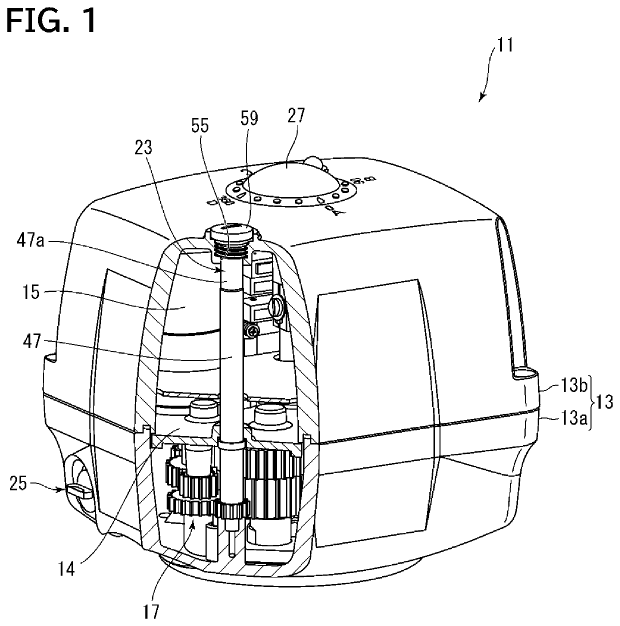
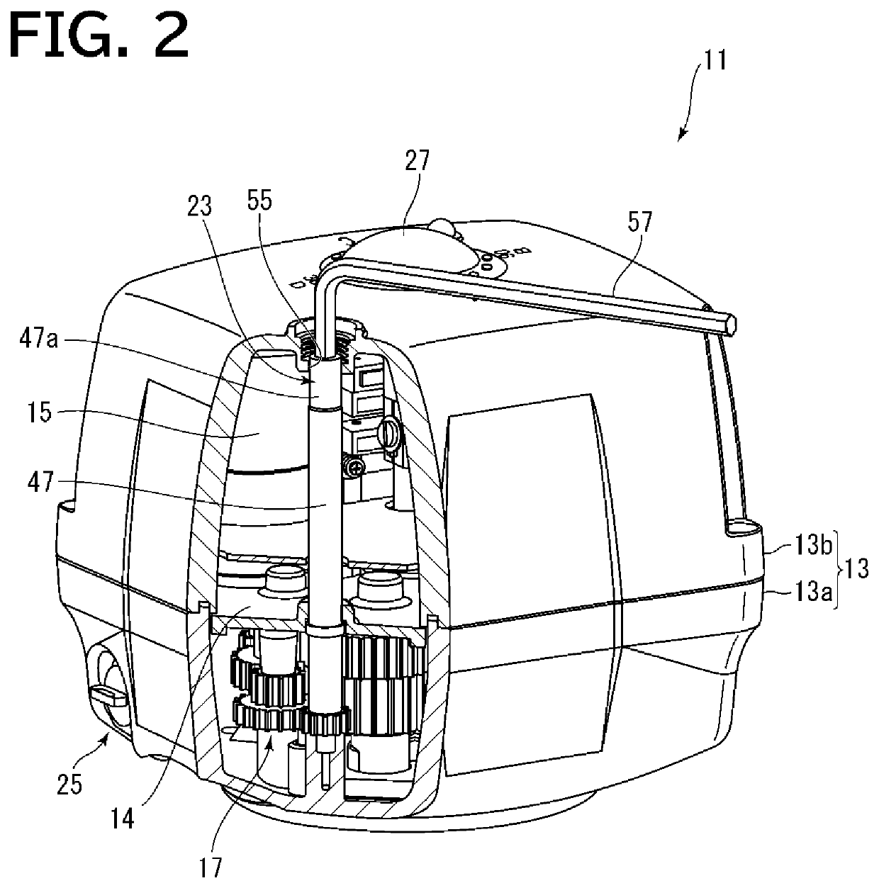
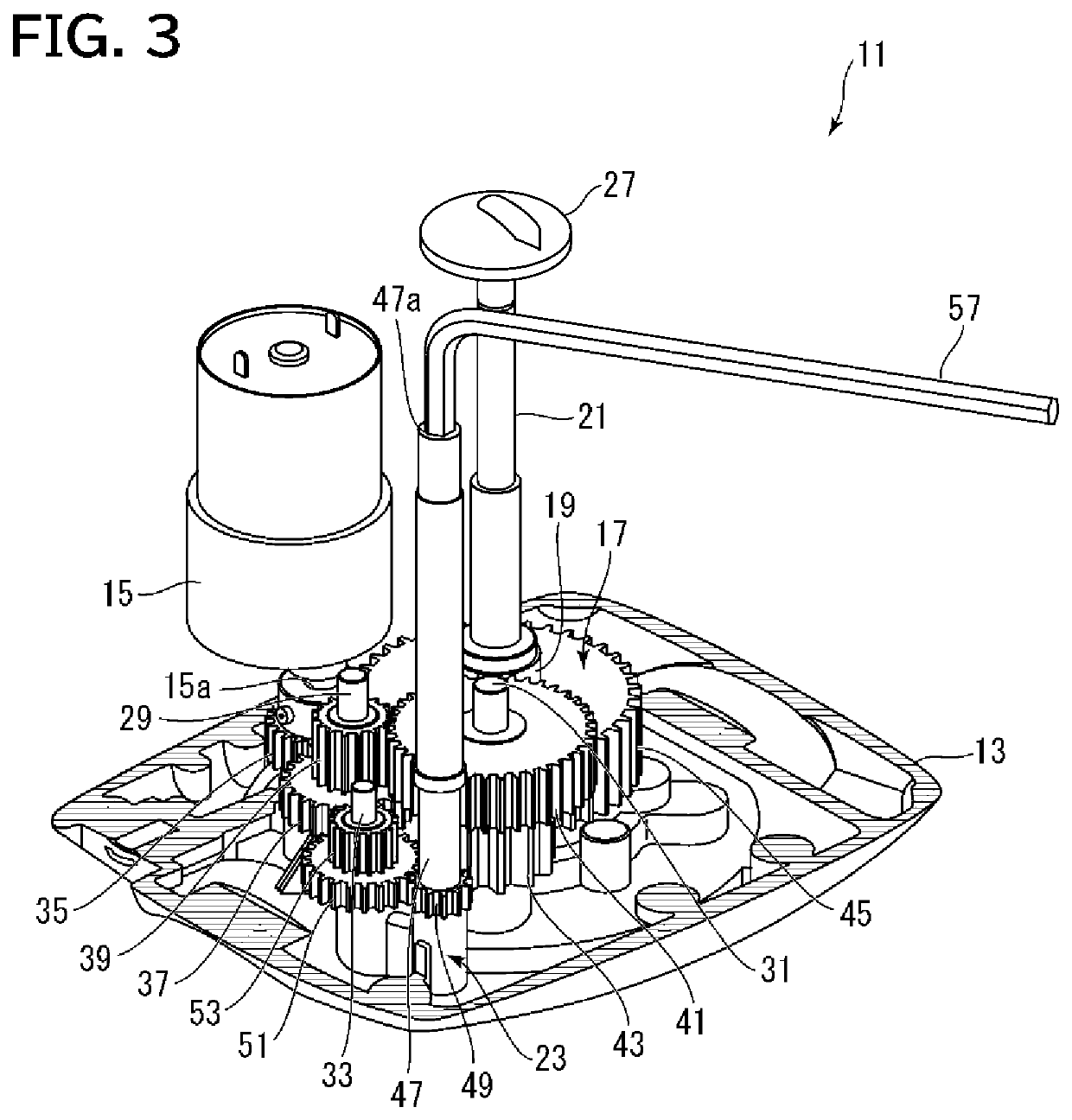
[0029]An embodiment of an electric actuator according to the present invention will be described below with reference to the drawings.

[0030]First, an overall configuration of the electric actuator according to the present invention will be described with reference to FIGS. 1 to 4. In the embodiment shown in FIGS. 1 to 4, an electric actuator 11 having a manual operation mechanism is exemplified as the electric actuator.

[0031]The electric actuator 11 includes a housing 13 having a generally box shape, an electric motor 15 serving as an electric driving unit arranged inside the housing 13, an output shaft 19 rotated by the rotation of a rotating shaft 15a of the electric motor 15 transmitted via a gear transmission mechanism 17, a control shaft 21 connected to an upper portion of the output shaft 19, a manual operation mechanism 23, and a power supply switching mechanism 25 for selectively switching between the supply and cutoff of power to the electric motor 15. By this configuration...


PUM


Abstract

An electric actuator includes a housing, an electric driving unit, an selector member being rotatable about a rotation axis and moving in a direction of the rotation axis, a position holding member and detection object provided in the selector member, a detector, an engagement groove provided on a cooperation surface inside the housing, and a biasing member biasing the selector member in the direction of the rotation axis to make the position holding member approach the cooperation surface. The engagement groove is formed so that the detection object is positioned in one of a detectable area and an undetectable area when the position holding member is engaged with the engagement groove, and the detector is configured to switch between supply and cutoff of power to the electric driving unit in accordance with whether or not the detection object is detected.

Description

TECHNICAL FIELD[0001]The present invention relates to an electric actuator that drives an output shaft connected to a valve or the like by means of an electric driving unit.BACKGROUND ART[0002]In a valve such as a ball valve and a butterfly valve, an electric actuator may be used as a drive device for opening and closing operations. The electric actuator is configured to transmit a driving force of an electric driving unit such as an electric motor to an output shaft (for example, stem) connected to a valve body of a valve, etc., to rotate the output shaft. There is also an electric actuator that includes a manual operation mechanism allowing an output shaft to be manually operated, in order to make a manual operation enabled in the event of maintenance, power outage, or the like.[0003]When the electric actuator is required to be manually operated or to be brought to an emergency stop, it is necessary to cut off the supply of power to the electric actuator by using a switch such as ...

Claims


Application Information

Patent Timeline
Patent Type & Authority Applications(United States)
IPC IPC(8): F16K31/05G01V11/00H02K7/14H02K5/04
CPCF16K31/05H02K5/04H02K7/14G01V11/00H01H3/20F16K31/055F16K35/04F16K37/0025H02K11/23H02K11/21
Inventor KOHSHOH, KENJIKAMIMURA, SHINOBU
Owner ASAHI YUKIZAI KOGYO CO LTD
Learn More