Array Substrate, Color Filter Substrate, and Manufacturing Methods Thereof, Display Panel and Display Device
a color filter substrate and substrate technology, applied in the field of display technology, can solve the problems of low switchover efficiency and increased cost of the prior art transparent display device, and achieve the effect of high switchover efficiency and simple operation
- Summary
- Abstract
- Description
- Claims
- Application Information
AI Technical Summary
Benefits of technology
Problems solved by technology
Method used
Image
Examples
embodiment 1
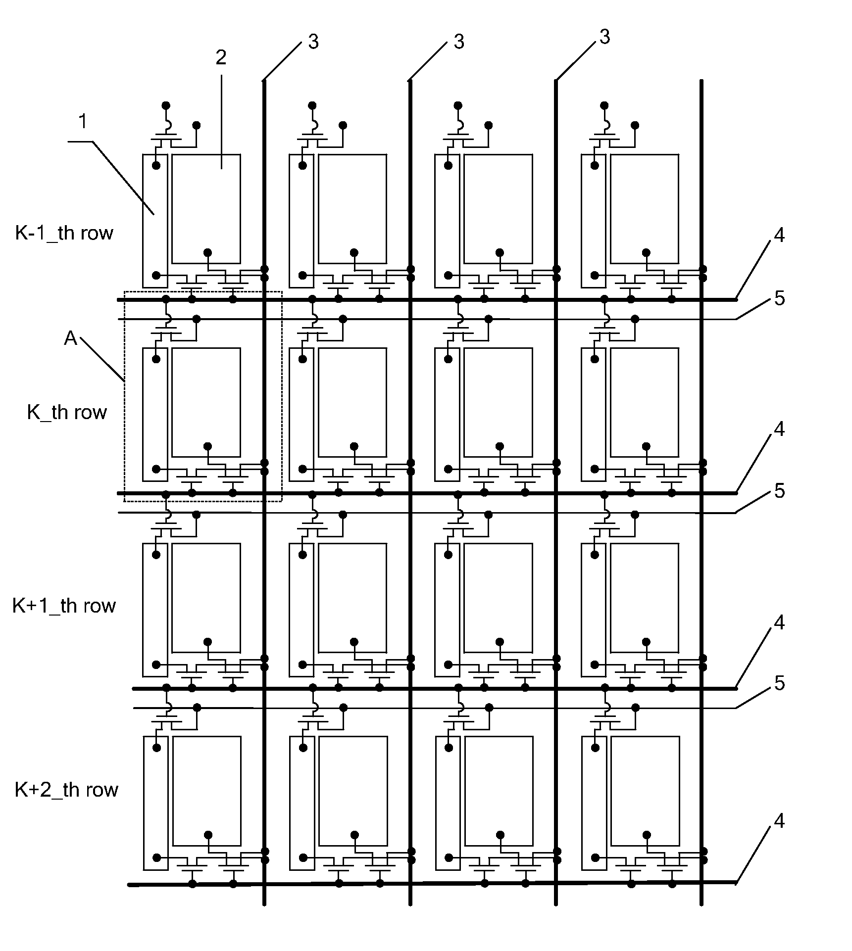
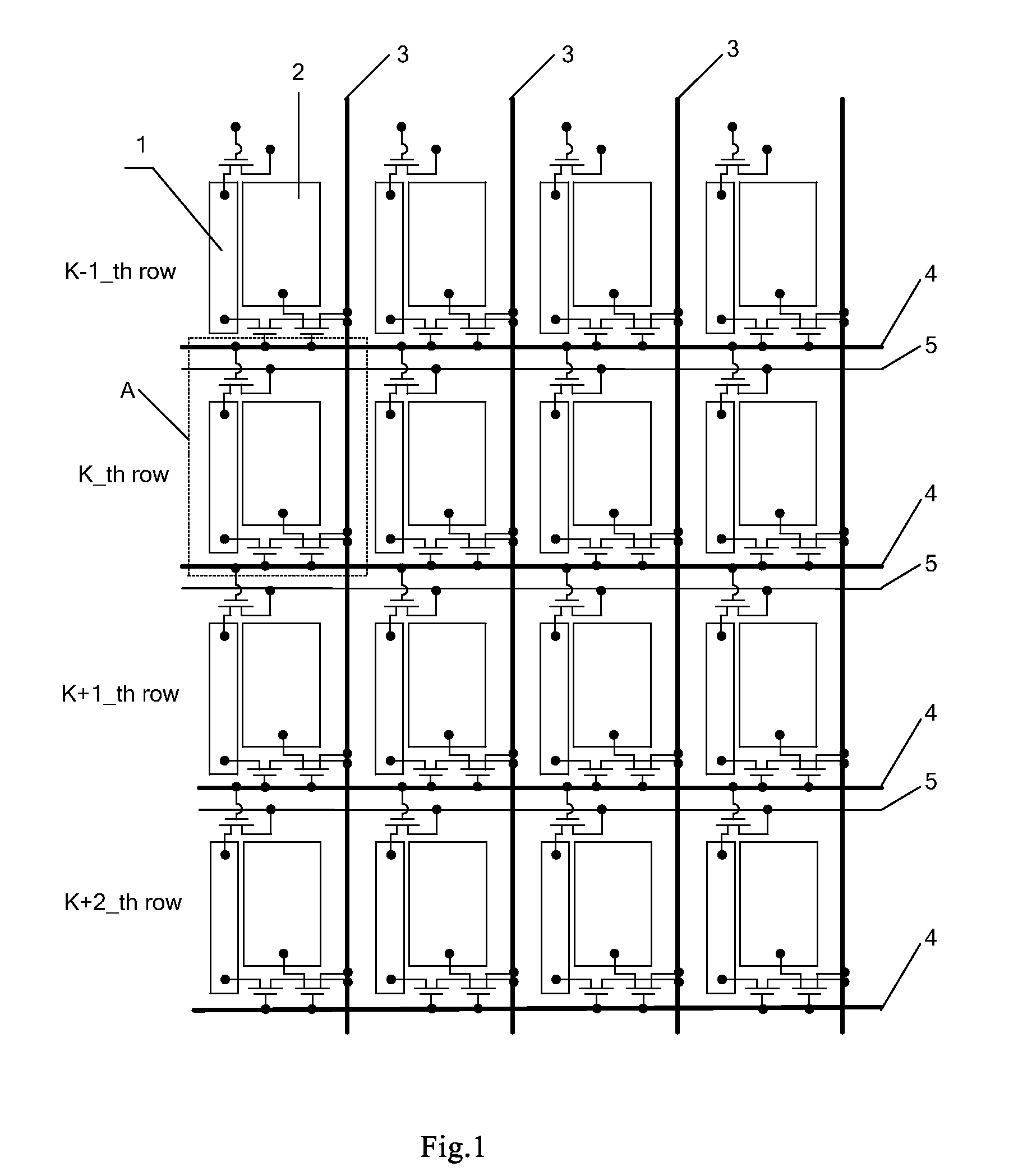
[0058]FIG. 1 is a schematic diagram of a structure of an array substrate provided by Embodiment 1 of the present invention, and FIG. 2 is a partially enlarged view of a structure A in FIG. 1. As shown in FIG. 1 and FIG. 2, the array substrate includes a plurality of gate lines 4 and a plurality of data lines 3, wherein the gate lines 4 and the data lines 3 define pixel units, and the pixel units each is provided therein with a second electrode 2 and switch units. A part or all of the pixel units each are provided therein with a first electrode 1, and the switch units are used for controlling the first electrode 1 and the second electrode 2 to be loaded with voltage signals. When the gate lines 4 are sequentially scanned, the first electrode 1 is loaded with a first voltage signal, and when the gate lines 4 are reversely scanned, the first electrode 1 is loaded with a second voltage signal; and when the gate lines 4 are sequentially scanned, the second electrode 2 is loaded with a th...
embodiment 2
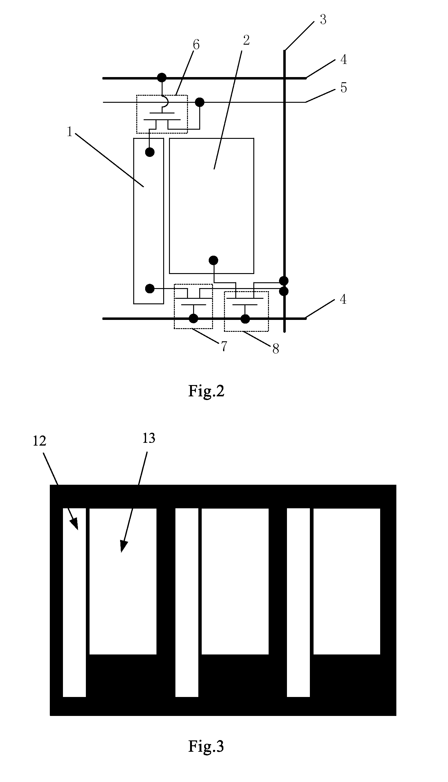
[0089]FIG. 5 is a schematic diagram of a partial structure of a color filter substrate provided by Embodiment 2 of the present invention. As shown in FIG. 5, the color filter substrate includes light blocking strips 10 provided on a second base substrate, by which a plurality of pixel regions are defined. The pixel region is formed therein with a color matrix pattern 9, and at least part of the pixel regions each is formed therein with a transparent pattern 11. In the example shown in FIG. 5, three adjacent light blocking strips 10 are shown, and the three light blocking strips 10 define three pixel units.
[0090]In this case, the color matrix pattern 9 may include a red matrix pattern R, a green matrix pattern G and a blue matrix pattern B, and of course, the color matrix pattern 9 may also be a matrix pattern of any other color. Meanwhile, the light blocking strip may be a black matrix or any other unit formed with a light blocking material.
[0091]In this embodiment, in a display dev...
embodiment 3
[0096]Embodiment 3 of the present invention provides a display panel, including an array substrate and a color filter substrate provided opposite to each other, wherein the array substrate provided by Embodiment 1 is adopted as the array substrate, the color filter substrate provided by Embodiment 2 is adopted as the color filter substrate, the pixel unit is provided in correspondence with the pixel region, the first electrode is provided in correspondence with the transparent pattern and the second electrode is provided in correspondence with the color matrix pattern. The details thereof may refer to the descriptions of Embodiments 1 and 2, and will not be redundantly described herein.
[0097]It is noted that, the display panel in Embodiment 3 includes any one of a Twisted Nematic (TN) panel, a Vertical Alignment (VA) panel, an In-Plane Switching (IPS) panel and a Fringe Field Switching (FFS) panel.
[0098]Embodiment 3 of the present invention provides a display panel, including an arr...
PUM
 Abstract
Description
Claims
Application Information
 - R&D
- Intellectual Property
- Life Sciences
- Materials
- Tech Scout
- Unparalleled Data Quality
- Higher Quality Content
- 60% Fewer Hallucinations
Browse by: Latest US Patents, China's latest patents, Technical Efficacy Thesaurus, Application Domain, Technology Topic, Popular Technical Reports.
© 2025 PatSnap. All rights reserved.Legal|Privacy policy|Modern Slavery Act Transparency Statement|Sitemap|About US| Contact US: help@patsnap.com


