Framing tool

a tool and frame technology, applied in the field of frame tools, can solve problems such as difficulty in retaining the orientation of the object with respect to the first axis, and achieve the effect of simplifying the framing of an elemen

a tool and frame technology, applied in the field of frame tools, can solve problems such as difficulty in retaining the orientation of the object with respect to the first axis, and achieve the effect of simplifying the framing of an elemen

US7546687B2Inactive Publication Date: 2009-06-16HAALA DAVID M

Image

  • Framing tool
  • Framing tool
  • Framing tool

Examples


Embodiment Construction

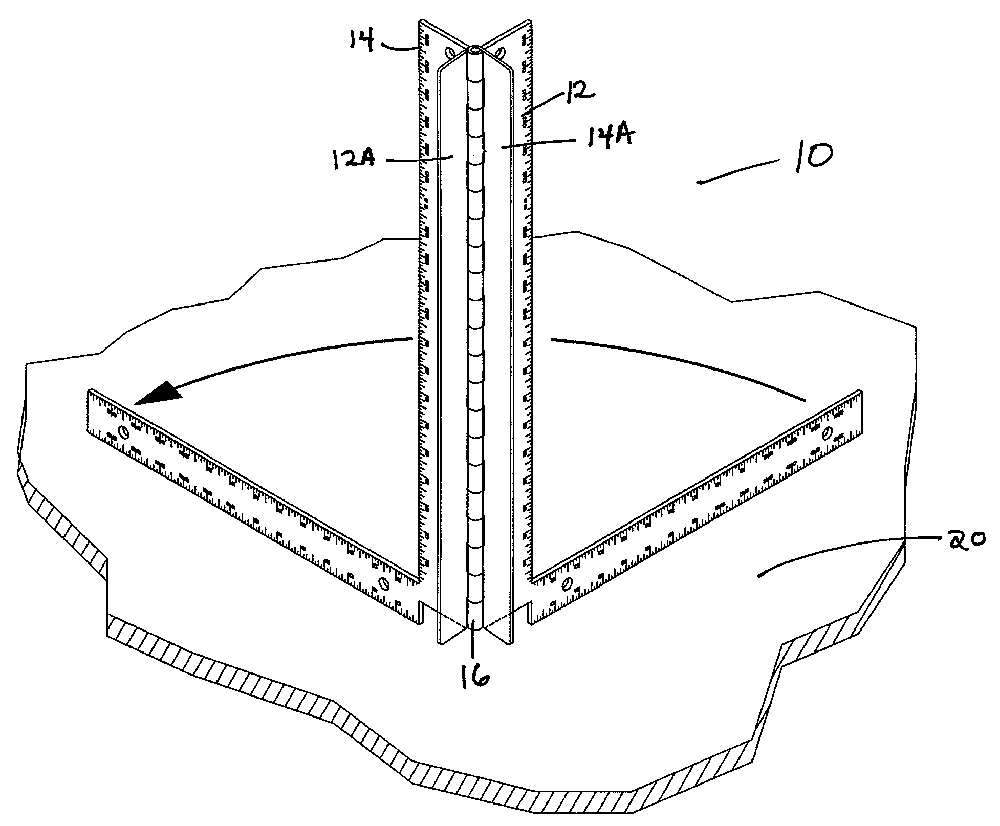
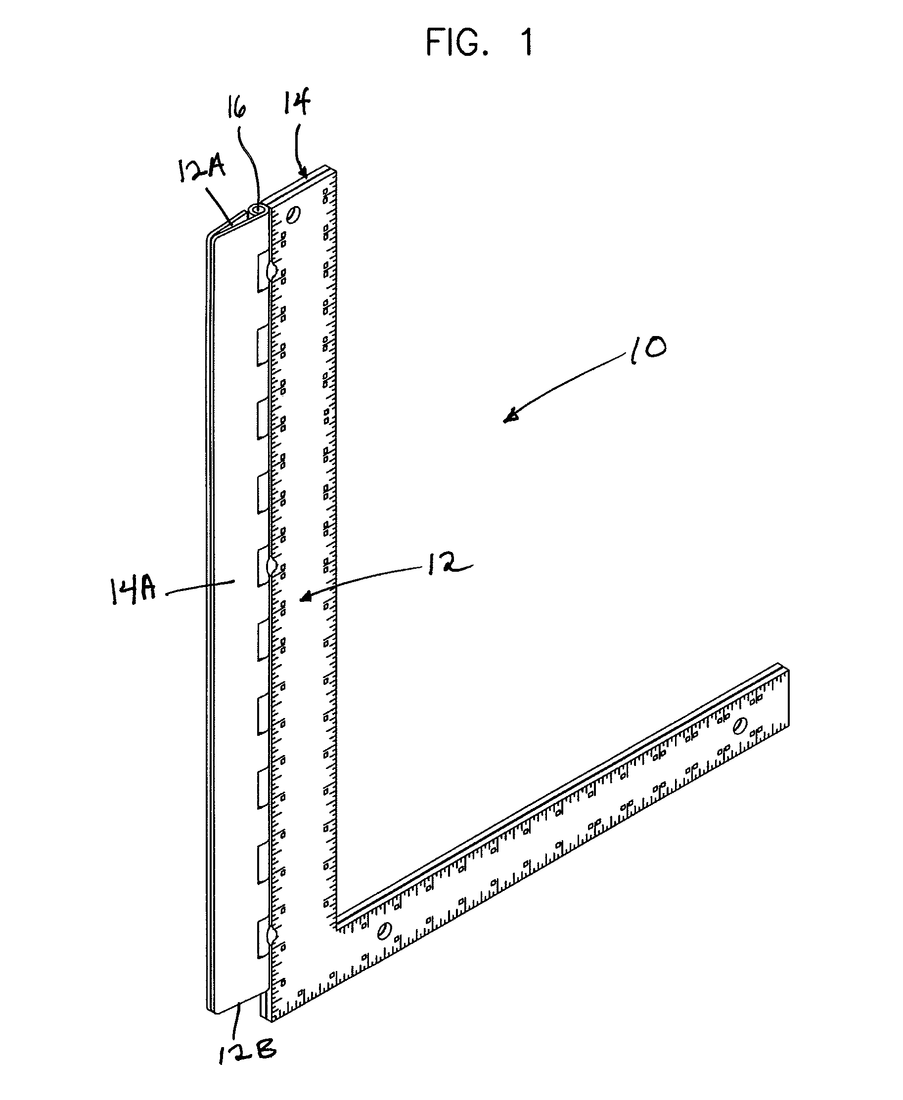
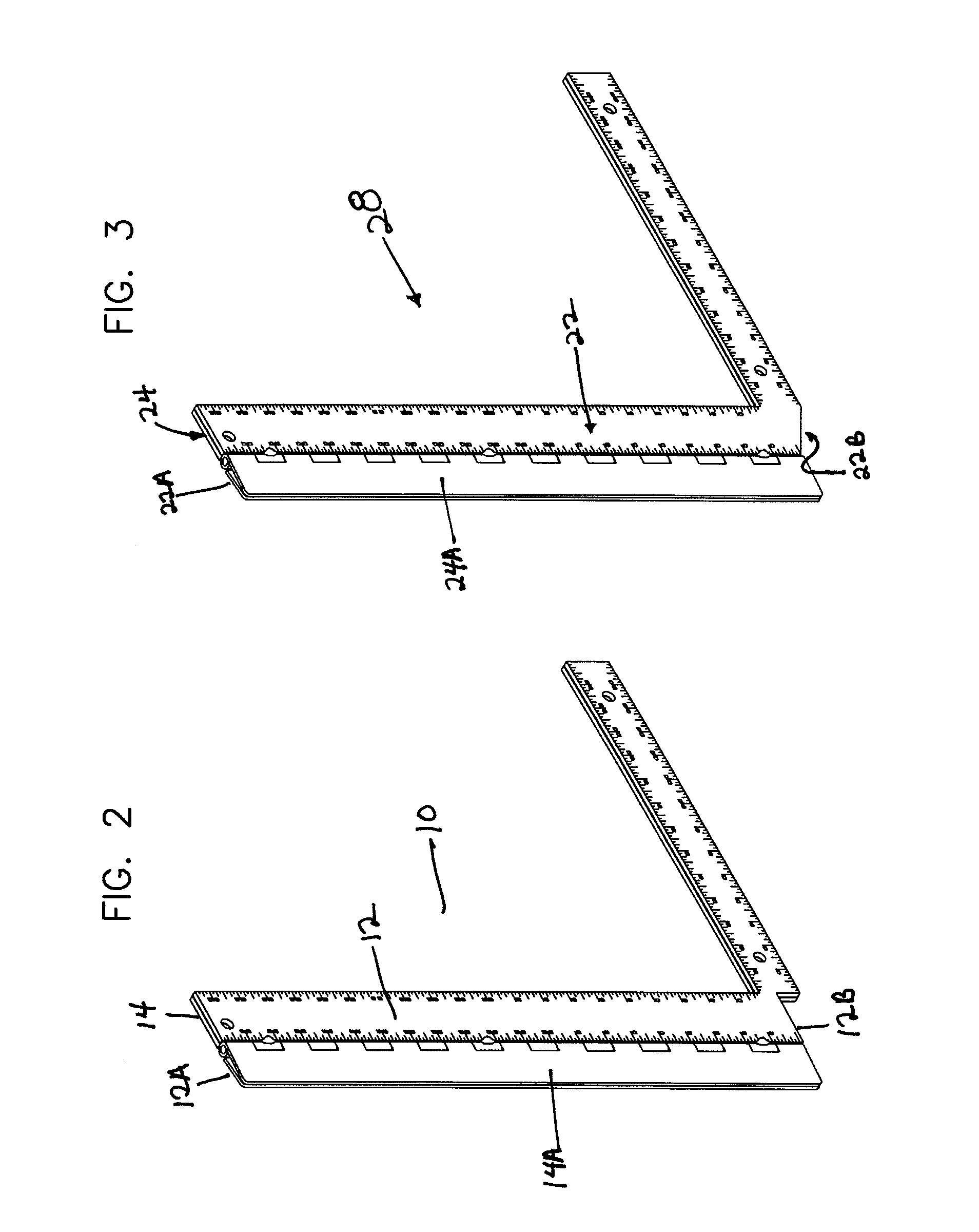
[0010]FIGS. 1 and 5 show a first embodiment of the present apparatus 10. Apparatus 10 has a first L-shaped square 12 and a second L-shaped square 14 pivotably attached together along one edge at hinge 16. First square 12 has a fin extension 12A, and second square 14 has a fin extension 14A; fins 12A, 14A extend outward from hinge 16. The lower ends of fin extensions 12A, 14A terminate to define notch 12B and substantially identical notch 14B. Notches 12B and 14B are provided to make performance of an operation such as welding more facile. FIG. 1 shows apparatus 10 folded while FIG. 5 shows the apparatus with first square 12 with an angular offset relative to the second square 14.

[0011]As shown in FIG. 4, with square 12 angularly offset from square 14, hinge 16 and apparatus 10, including first fin extension 12A and second fin extension 14A, will all be oriented perpendicular to the plane 20.

[0012]FIG. 5 shows apparatus 10 arranged substantially the same as in FIG. 4 with respect to ...


PUM


Abstract

Apparatus using two hinged L-shaped squares to determine perpendicular with respect to a plane. Placing the apparatus against a plane with the squares offset angularly with respect to each other and placing an object to be secured to a plane adjacent to the hinge within fins parallel to the hinge permits securing the object perpendicular to the plane with one hand while holding the apparatus and object with the other hand.

Description

FIELD OF THE INVENTION[0001]The present invention is a tool for measuring and defining a vertical relationship of an elongated member with respect to a plane using only one measurement and further using the same apparatus to orient an object perpendicular to the same plane to simplify framing.BACKGROUND OF THE INVENTION[0002]In construction and assembly it is frequently necessary to orient an element perpendicular to a plane. This is usually accomplished by utilizing a square to define the vertical with respect to one axis of a plane. The process is then repeated with respect to a second intersecting axis. The problem with this approach is the difficulty in retaining the orientation of the object with respect to the first axis when defining the second axis.SUMMARY OF THE INVENTION[0003]This apparatus permits orientating an elongate element perpendicular to a plane with respect to two intersecting axes angled relative to each other. The apparatus incorporates two right angle squares ...

Claims


Application Information

Patent Timeline
16 Jun 2009
Publication
US7546687B2
IPC
B43L7/12
CPC
B43L7/027; B43L7/12; G01B3/04; G01B3/566
Inventors
HAALA, DAVID M.