Transverse car body conveying system

a conveying system and car body technology, applied in transportation and packaging, propulsion railway systems, rope railways, etc., can solve the problems of high conveying power requirement, low storage efficiency, and high carrier weight, and achieve stable carrier travel and high storage efficiency.

Inactive Publication Date: 2007-10-25
TSUBAKIMOTO CHAIN CO
View PDF3 Cites 6 Cited by
  • Summary
  • Abstract
  • Description
  • Claims
  • Application Information

AI Technical Summary

Benefits of technology

[0011] The skid-type carrier has a car body mounted thereon in transverse orientation with respect to the direction of carrier travel along the conveyor path, and is passively propelled along a pair of rails by a frictional driving force imparted by a drive roller. The friction bar, which extends along the direction of carrier travel, can be much shorter than the front-to-rear dimension of the car being transported. The size of the skid-type carrier can be relatively small compared to the conventional carrier, and consequently a high storage efficiency can be realized. Moreover, the power required to propel the carrier along the conveying path is substantially lower than the power required in a conventional conveyor. Moreover, since different types of car bodies generally do not differ greatly in their widths, the carrier can be compatible with a wide variety of car bodies.
[0012] Because the friction bar and the driving roller are provided on the center line of the car body conveying path, stable travel of the carrier can be attained, and the frame of the skid-type carrier can be structurally very simple.

Problems solved by technology

The lengths of the conveyor tracks 200 need to be sufficiently large to accommodate the car body lengths w1, and consequently storage efficiency is low.
Moreover, the carrier size is necessarily large, resulting in high carrier weight and a high conveying power requirement.
Opening of a car door during operation of the conveyor can cause damage to objects adjacent to the conveying path, as well as injury to personnel.
However, these ropes take up space, and become an obstacle to various operations, impairing productivity.

Method used


Image

  • Transverse car body conveying system
  • Transverse car body conveying system
  • Transverse car body conveying system

Examples


Embodiment Construction

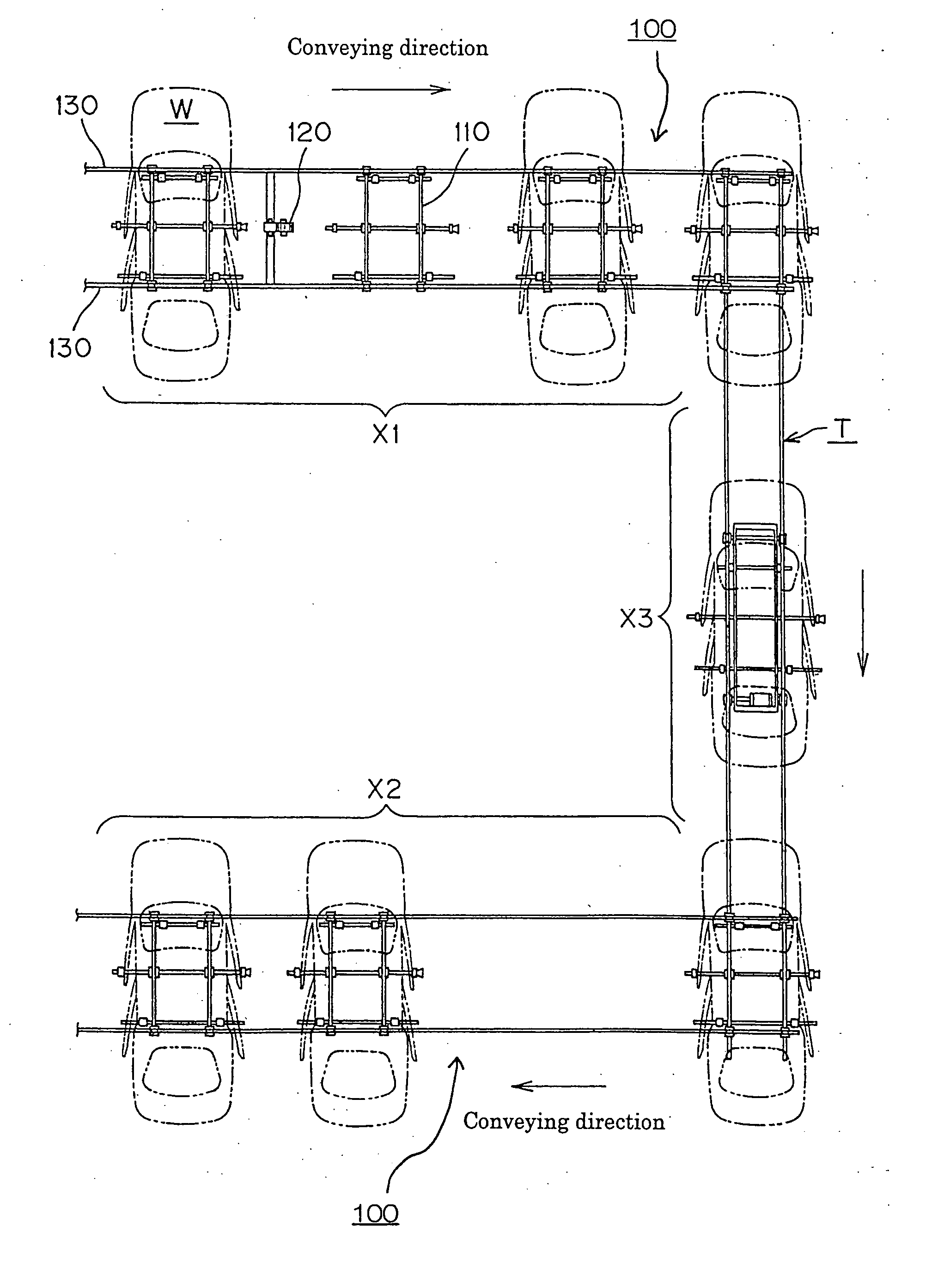
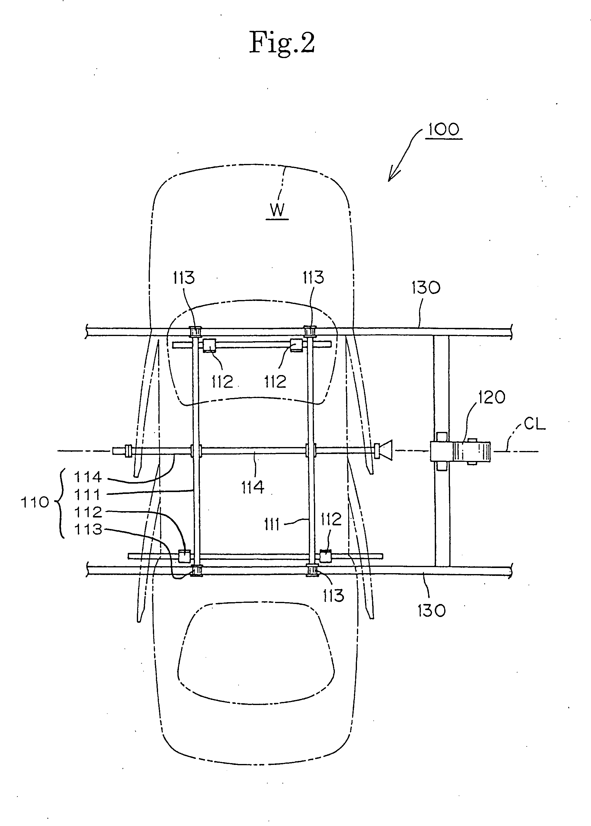
[0022] In the transverse car body conveying system shown in FIG. 1, car bodies may be transported along conveying path X1 in a painting step, and along conveying path X2 in a drying step. The car bodies are transferred along a conveying path X3 from passage X1 to passage X2 by a traverser mechanism T. Each of the car bodies is arranged so that its direction of elongation, i.e., its long dimension, is in transverse relationship to its direction of travel along passages X1 and X2, and the entire conveying system of FIG. 1 is generally C-shaped in plan view.

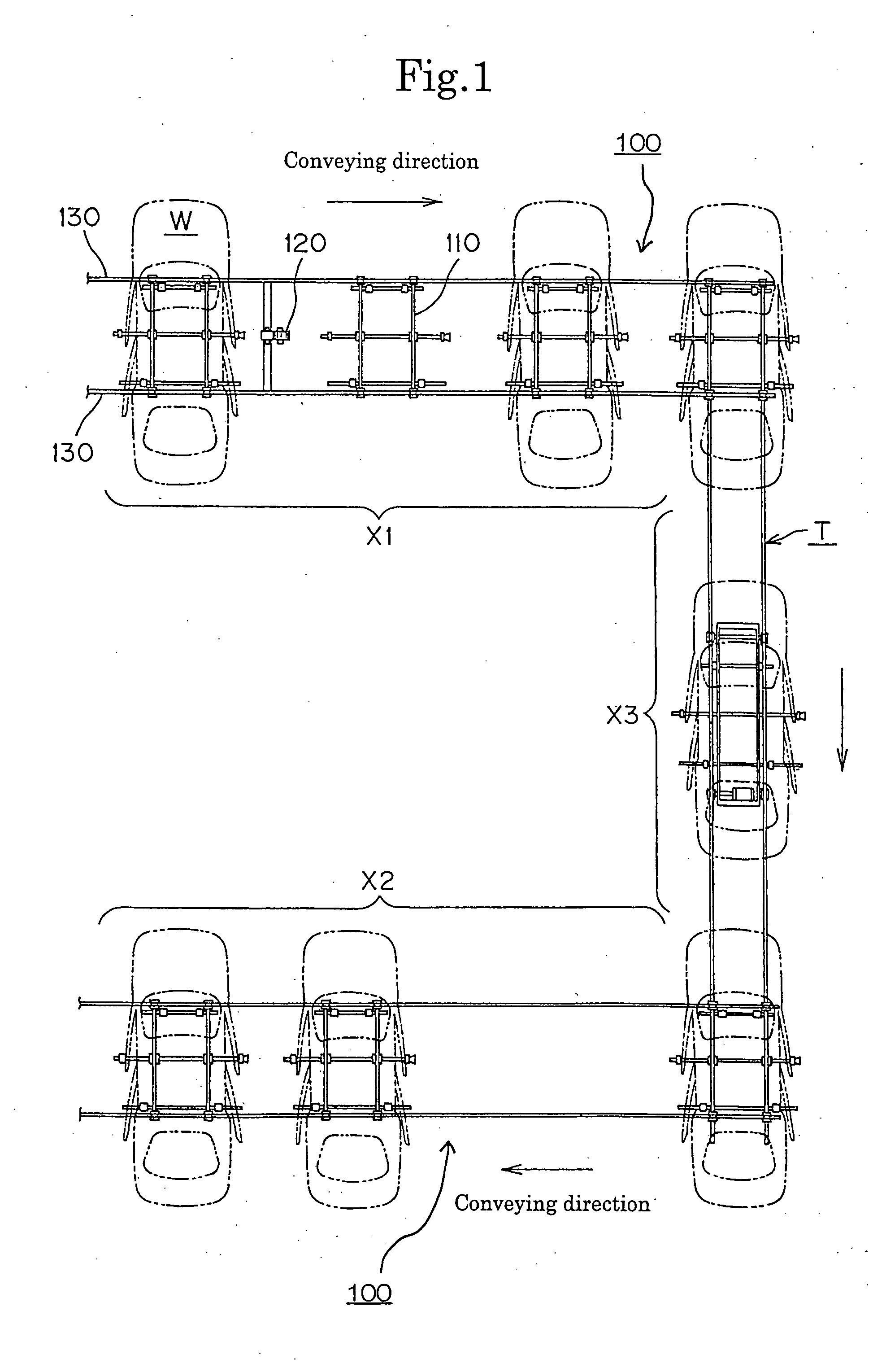
[0023] Skid-type carriers 110 for mounting the transversely oriented car bodies W, travel passively on a pair of left and right rails 130 provided along conveying paths X1 and X2. The carriers are propelled by driving forces imparted by friction drive rollers located along each of the car body conveying paths X1 and X2. The drive roller mechanism 120 for conveying path X1 is shown in FIG. 1.

[0024] The skid-type carrier 110 as show...


PUM


Abstract

A skid-type car body carrier carries a transversely oriented car body along a conveying path. The carrier is driven by a drive roller which is biased upwardly and frictionally engages the bottom of a centrally located friction bar mounted underneath the carrier.

Description

CROSS-REFERENCE TO RELATED APPLICATIONS [0001] This application is a continuation of application Ser. No. 11 / 018,879, filed Dec. 21, 2004, and claims priority on the basis of Japanese patent application 2004-054318, filed Feb. 27, 2004.FIELD OF THE INVENTION [0002] This invention relates to a transfer system for conveying car bodies in a factory, and more specifically to a transverse car body conveying system, in which a skid-type carrier travels passively on rails, and on which a car body mounted on the carrier is oriented in a direction transverse to the direction of carrier movement. BACKGROUND OF THE INVENTION [0003] Known car body conveying systems include systems having a number of conveyor units, in which a large number of hybrid conveying carriers travel. Each conveying carrier is provided with left and right conveying skids, left and right front wheels, and left and right rear wheels. The hybrid type carriers are propelled by driving rollers and controlled by a large number...

Claims


Application Information

Patent Timeline
Patent Type & Authority Applications(United States)
IPC IPC(8): B61B9/00B61B13/12B62D65/18
CPCB61B13/127Y02T30/30B62D65/18Y02T30/00
Inventor UENO, ICHIROOSAWA, MANABUMATSUSHITA, TOSHIHIROYOSHIMURA, NOBUHIKOTOBA, KAZUO
Owner TSUBAKIMOTO CHAIN CO
Why Eureka
Try Eureka