Tubular skylight dome with variable prism

a skylight dome and variable prism technology, applied in the field of skylights, can solve the problems of difficult to achieve, difficult to provide, and the skylight can over-illuminate a room, and achieve the effect of constant light outpu

Active Publication Date: 2009-06-16
SOLATUBE INT INC
View PDF61 Cites 46 Cited by
  • Summary
  • Abstract
  • Description
  • Claims
  • Application Information

AI Technical Summary

Problems solved by technology

As recognized herein, a difficult goal of skylight design is the provision of as constant a light output as possible regardless of the time of day.
This is difficult to achieve because in the mornings and evenings the sun is at a low angle and less light enters the skylight than at midday, when the sun is at a high angle.
Indeed, in designing a skylight to maximize light collection and throughput during the morning and evenings hours, the resulting skylight can over-illuminate a room at midday, with so-called “hotspots” (areas in the room where light from the skylight undesirably might be focused) being particularly noticeable at midday.

Method used


Image

  • Tubular skylight dome with variable prism
  • Tubular skylight dome with variable prism
  • Tubular skylight dome with variable prism

Examples


Embodiment Construction

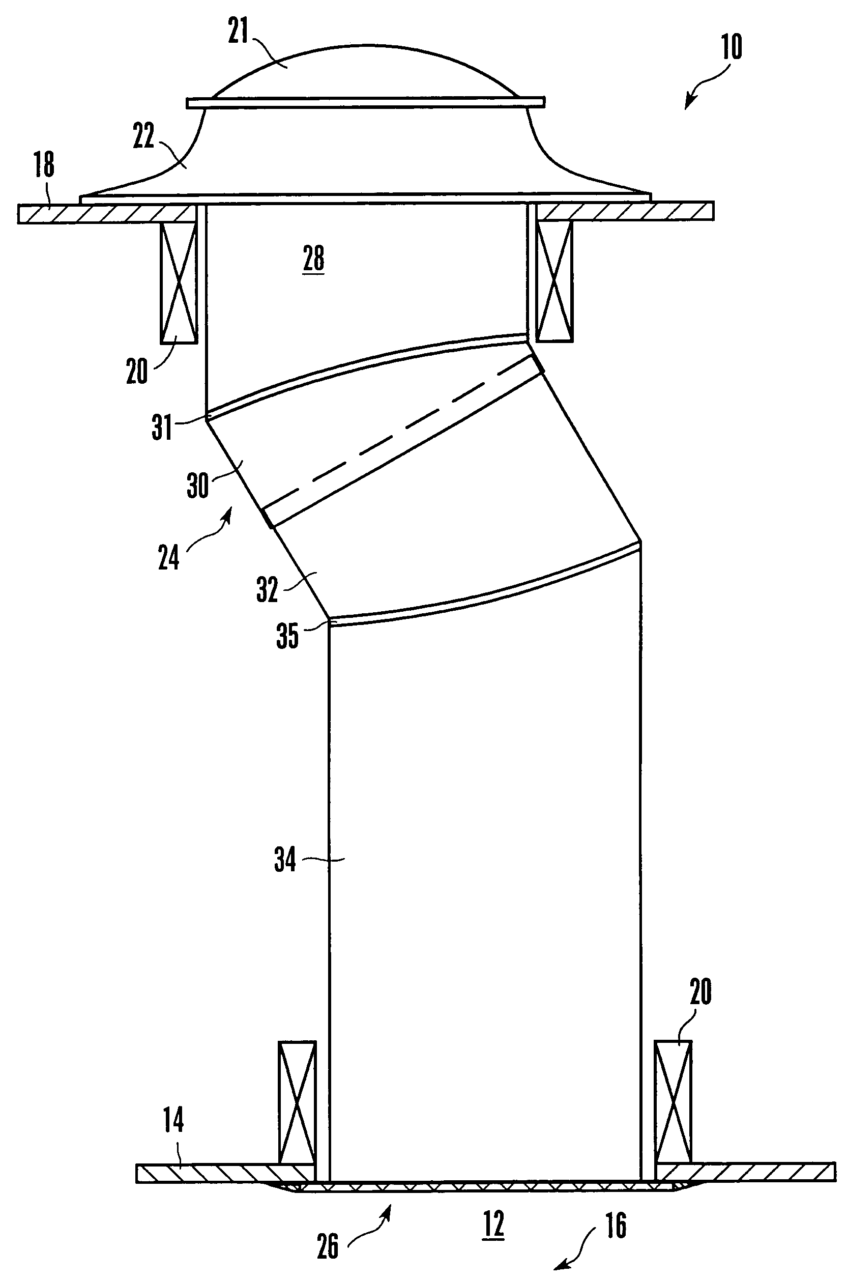
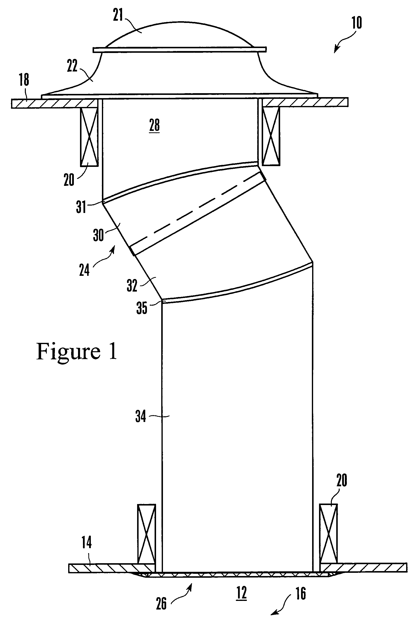
[0018]Referring initially to FIG. 1, an exemplary non-limiting tubular skylight made in accordance with the present invention is shown, generally designated 10, for lighting, with natural sunlight, an interior room 12 having a ceiling surface 14, e.g., drywall, acoustic tile, etc., in a building, generally designated 16. FIG. 1 shows that the building 16 has a roof 18 and one or more joists 20 that support the roof 18 and ceiling surface 14.

[0019]As shown in FIG. 1, the skylight 10 includes a rigid hard plastic roof-mounted cover 21 that can be made of, e.g., acrylic or polycarbonate or glass. The cover 21 is optically transmissive and preferably is transparent, and details concerning it are discussed further below.

[0020]The cover 21 may be mounted to the roof 18 by means of a ring-like metal flashing 22 that is attached to the roof 18 by means well-known in the art. The metal flashing 22 can, be angled as appropriate for the cant of the roof 18 to engage and hold the cover 21 in th...


PUM


Abstract

The inside surface of a cover for a skylight is molded to have a variable prism that directs low-angle light into the skylight tube and that reflects away some high-angle light, to achieve a more constant light output over the course of the day. The prism is established by a series of circular parallel grooves, with grooves nearer the apex of the cover having cross-sections that are different than the cross-sections of grooves nearer the periphery of the cover.

Description

FIELD OF THE INVENTION[0001]The present invention relates to skylights.BACKGROUND OF THE INVENTION[0002]Skylights are used to illuminate buildings in a pleasing and energy-conserving way. Tubular skylights such as those made by the present assignee typically have a roof-mounted transparent cover or dome, a light conveying tube assembly extending down from the dome into the building to a ceiling, and a light diffuser plate covering the bottom of the tube at the ceiling. An example of a commercially successful tubular skylight is disclosed in U.S. Pat. No. 5,099,622, assigned to the same assignee as the present invention and incorporated herein by reference. Other patents owned by the present assignee that pertain to various skylight technologies are disclosed in U.S. Pat. Nos. RE36,496 (dome with reflector), 6,219,977 (round-to-square adapter), and 5,896,712 (dome with circular grooves), all of which are incorporated herein by reference.[0003]As recognized herein, a difficult goal of...

Claims


Application Information

Patent Timeline
Patent Type & Authority Patents(United States)
IPC IPC(8): E04B7/18G02B17/00G02B3/08
CPCE04D13/03E04D13/033F21S11/00F21V5/02E04D2013/0345
Inventor JASTER, PAULFUTHEY, JOHN
Owner SOLATUBE INT INC
Why Eureka
Try Eureka