Focus detecting and controlling device of aerial camera

An aerial camera, focusing technology, applied in focusing devices, cameras, optics, etc., can solve problems such as multi-focus time

Inactive Publication Date: 2010-08-18
CHANGCHUN INST OF OPTICS FINE MECHANICS & PHYSICS CHINESE ACAD OF SCI
View PDF2 Cites 15 Cited by
  • Summary
  • Abstract
  • Description
  • Claims
  • Application Information

AI Technical Summary

Problems solved by technology

Because it is judged point by point, the energy of the point can only be judged after each point has passed through, so more focus detection time will be used, and the accuracy is inversely proportional to the number of moving step distances. In a certain focus detection time Within, the accuracy will not be very high

Method used


Image

  • Focus detecting and controlling device of aerial camera
  • Focus detecting and controlling device of aerial camera
  • Focus detecting and controlling device of aerial camera

Examples


Embodiment Construction

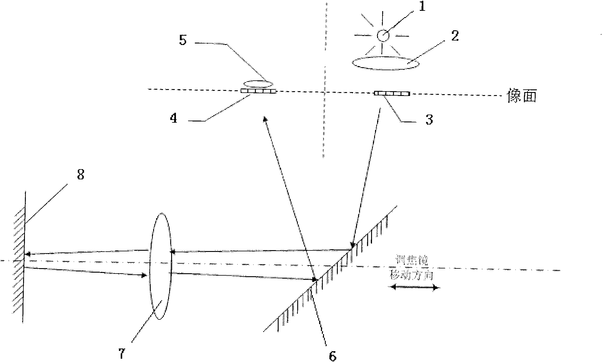
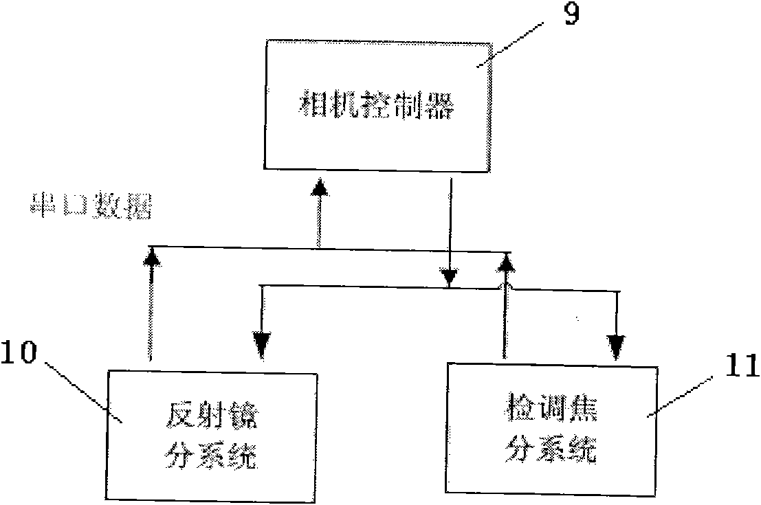
[0021] like figure 1 , 2 As shown, the focus detection and adjustment device in the prior art includes a constant light source 1 , a diffuser mirror 2 , a transmitter grating 3 , a receiver grating 4 , an optoelectronic device 5 and a focus detection subsystem 11 . The emitter grating 3 is placed on the image surface of the camera as a target, and the constant light source 1 illuminates one side of the emitter grating 3 and reflects it to the vicinity of the receiver grating 4 on the image surface through the camera optical system. When checking the focus, the camera controller 9 sends a focus checking command to the camera mirror subsystem 10, and the mirror subsystem 10 controls the scanning mirror 8 in the camera optical system to make a small swing on the position vertical to the optical axis, so that the grating on the transmitting side 3. The image formed on the image plane scans the receiving grating 4, and the photoelectric device 5 receives the light energy passing t...


PUM


Abstract

The invention relates to a focus detecting and controlling device of an aerial camera. The device is provided with three transmitting party grids and three receiving party grids which are respectively arranged above an image surface, on the image surface and below the image surface; rays emitted by a constant light source illuminate one side of each transmitting party grid by a scattering mirror and are reflected to the vicinity of a corresponding receiving party grid by a camera optical system, light energy transmitting the three receiving party grids is respectively received by three photovoltaic devices, and a focusing controller collects the peak voltage values of the three photovoltaic devices, judges the optimal focusing plane position and drives a focusing reflector to move to the optimal focusing plane position for a camera to image. Because each of the transmitting party grids and each of the receiving party grids respectively comprise the three grids which are respectively arranged above the image surface, on the image surface and below the image surface, the distance difference of the three grids in an optical path is the focal depth of a one-time camera optical system so that the information of collected peak voltage values is surely different at the same time to benefit the judgment of the focusing plane position, save the focus-detecting time and improve the focus-detecting precision.

Description

technical field [0001] The invention relates to an aerial camera detection and focusing device. Background technique [0002] When an aerial camera is imaging in the air, changes in temperature, atmospheric pressure, and photographing distance will cause defocusing, which seriously affects the clarity and resolution of the image, especially for long-focus cameras. Therefore, in order to obtain high-definition images, the camera needs to automatically check and adjust the focus before taking pictures. [0003] At present, the commonly used focus detection and adjustment device on aerial cameras is the photoelectric self-collimation type. The device includes a constant light source, a scattering mirror, a transmitting grating, a receiving grating, a photoelectric device and a focusing subsystem. The emitter grating and the receiver grating are placed on the image surface of the camera, and the light emitted by the constant light source illuminates one side of the emitter gra...

Claims


Application Information

Patent Timeline
Patent Type & Authority Applications(China)
IPC IPC(8): G03B13/32
Inventor 陈志超匡海鹏史磊张雪菲张景国刘明
Owner CHANGCHUN INST OF OPTICS FINE MECHANICS & PHYSICS CHINESE ACAD OF SCI
Why Eureka
Try Eureka