
An automatic focusing device and method

An automatic focusing and focusing technology, applied in optics, instruments, photography, etc., can solve the problems of photoreceptor deviation, economic loss, difficult to determine the coaxial accuracy, etc., to achieve stable focusing process, high focusing accuracy, The effect of a high degree of automation

Active Publication Date: 2018-01-23
SUZHOU FORKINS ELECTRONICS TECH CO LTD
View PDF5 Cites 0 Cited by
  • Summary
  • Abstract
  • Description
  • Claims
  • Application Information

AI Technical Summary

Problems solved by technology

Due to various reasons such as camera processing technology and handling, the photoreceptor of the camera may deviate from this optimal imaging surface, resulting in poor imaging of the camera, so the focal length of the camera needs to be adjusted
[0004] It is difficult to determine the coaxial accuracy of the existing focusing mechanism with other fixed axes during installation, and there are problems such as difficult installation and adjustment and large focusing errors. At the same time, some of the focusing rings used in the current focusing mechanism are made of stainless steel. Due to the high hardness of stainless steel, it is very easy to cause defects such as scratches or bumps on the surface of the camera module, resulting in certain economic losses. Some focus rings are made of plastic. Due to the poor heat resistance of plastic and easy aging or deformation, frequent repairs are required. Replacement is not conducive to improving production efficiency and saving costs

Method used


Image

  • An automatic focusing device and method
  • An automatic focusing device and method

Examples


Embodiment Construction

[0032] The following will clearly and completely describe the technical solutions in the embodiments of the present invention with reference to the accompanying drawings in the embodiments of the present invention. Obviously, the described embodiments are only some, not all, embodiments of the present invention. Based on the embodiments of the present invention, all other embodiments obtained by persons of ordinary skill in the art without creative efforts fall within the protection scope of the present invention.

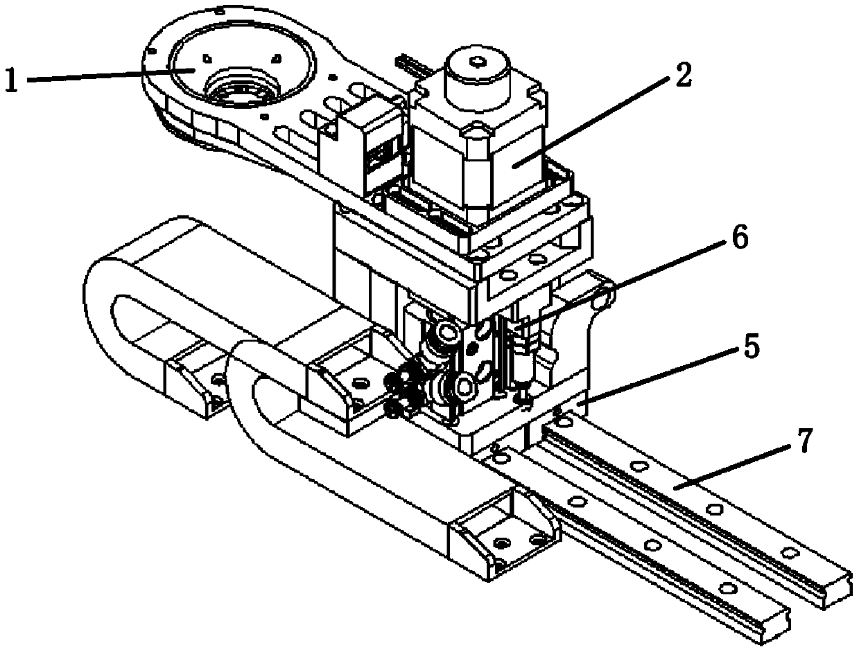
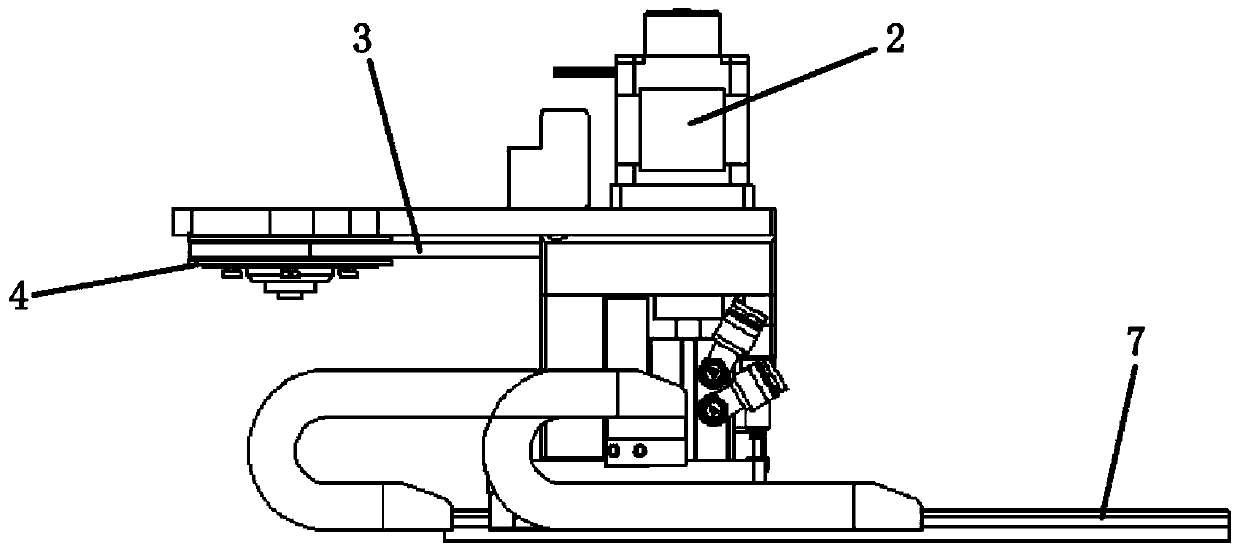
[0033] In one embodiment, such as figure 1 and figure 2 As shown, the present invention provides a kind of automatic focusing device, and this device comprises installation bottom surface, the slide rail 7 that is arranged on installation bottom surface, focusing ring 1 and driving mechanism, and described driving mechanism comprises focusing ring driving mechanism 2, The first drive mechanism 5 and the second drive mechanism 6, the focus ring drive mechanism 2 d...


PUM


Abstract

The invention relates to the field of mechanical automation equipment, and discloses an automatic focusing device, which includes a mounting bottom surface, a slide rail arranged on the mounting bottom surface, a focusing ring and a driving mechanism, and the driving mechanism includes a focusing ring driving mechanism and a first driving mechanism. and the second drive mechanism, the focus ring drive mechanism drives the focus ring to rotate, the first drive mechanism drives the focus ring to move in a direction parallel to the installation bottom surface, the second drive mechanism drives the focus ring to move in a direction perpendicular to the installation bottom surface, and the second drive mechanism drives the focus ring to move in a direction perpendicular to the installation bottom surface. A first connecting piece is arranged between the first driving mechanism and the second driving mechanism, and a second connecting piece is arranged between the second driving mechanism and the focusing ring; the focusing ring in the present invention is made of polyether ether ketone resin material , which effectively avoids scratches or bumps on the focus ring of the camera under test during the focusing process, ensures higher position accuracy and focus accuracy through the drive mechanism and sensors, and at the same time, improves work efficiency and shortens focus time through automated equipment .

Description

technical field [0001] The invention relates to the field of mechanical automation equipment, in particular to an automatic focusing device and method. Background technique [0002] At present, with the development of electronic technology, the demand for cameras on various electronic products, such as mobile phones and laptop computers, is increasing, and the dependence on image technology is getting higher and higher, and the pixel value of cameras is also getting higher and higher. Therefore, the requirements for the clarity of the images captured by the camera are also stricter, and correspondingly higher requirements are put forward for the product quality of the camera. [0003] The optical lens of each camera has a certain focal length, that is, there is an optimal imaging surface. Due to various reasons such as camera processing technology and handling, the photoreceptor of the camera may deviate from this optimal imaging surface, resulting in poor imaging of the ca...

Claims


Application Information

Patent Timeline
Patent Type & Authority Patents(China)
IPC IPC(8): G03B43/00G03B13/36
Inventor 朱贵峰曹黎明毕研洋
Owner SUZHOU FORKINS ELECTRONICS TECH CO LTD
Learn More