Wheelbarrow

a wheelbarrow and wheel body technology, applied in the field of two-wheeled wheelbarrows, can solve the problems of considerable user strength

Inactive Publication Date: 2009-06-16
MORRIS RICHARD J
View PDF14 Cites 13 Cited by
  • Summary
  • Abstract
  • Description
  • Claims
  • Application Information

AI Technical Summary

Benefits of technology

[0003]It is an object of the present invention to provide a wheelbarrow that overcomes, or substantially ameliorates, the aforementioned shortcomings of the prior art, or at least provides a useful alternative.

Problems solved by technology

When these wheelbarrows carry a heavy load, they require considerable strength of the user to tip the wheelbarrow forward by pivotal motion about its front wheel.

Method used


Image

  • Wheelbarrow
  • Wheelbarrow
  • Wheelbarrow

Examples


Embodiment Construction

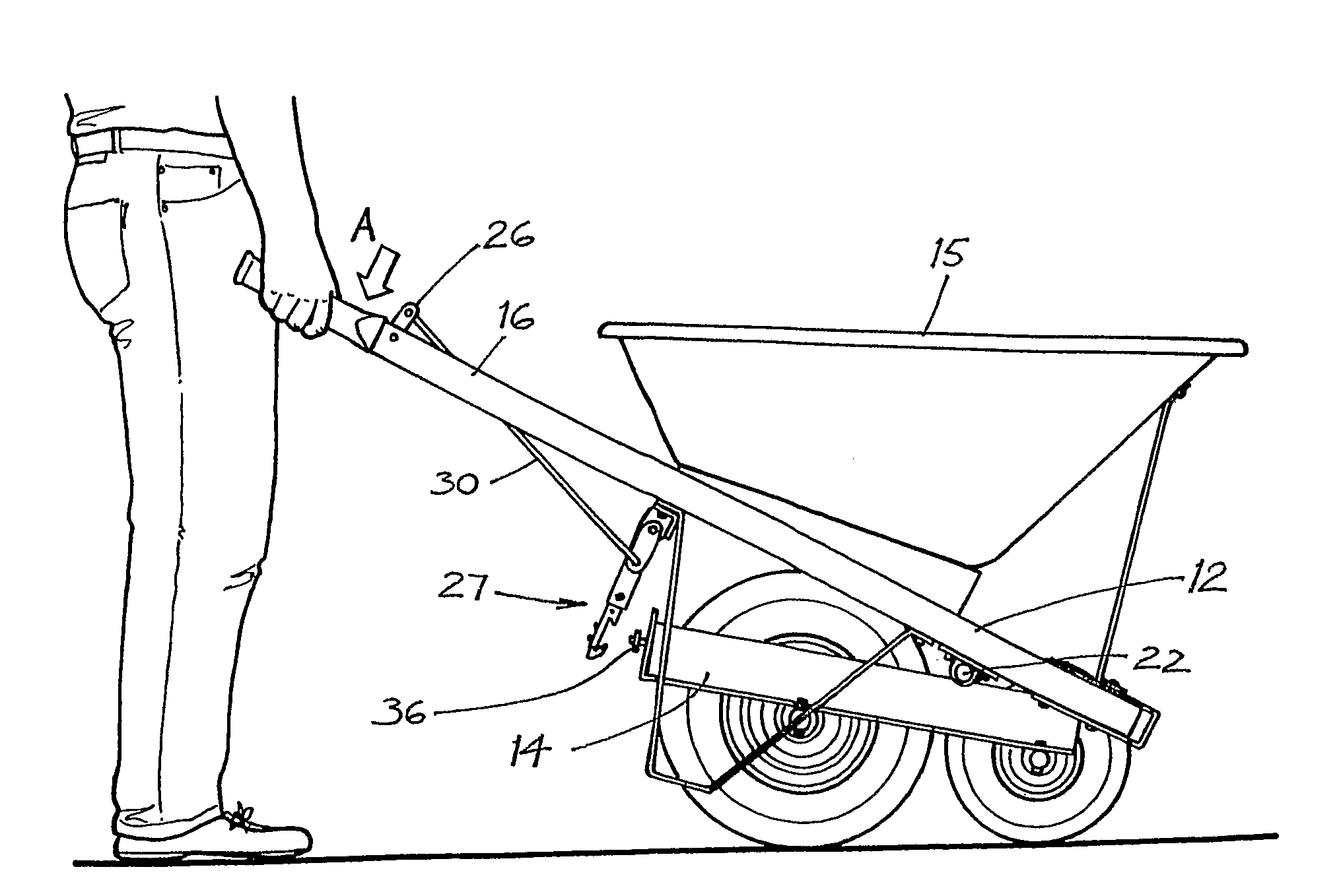
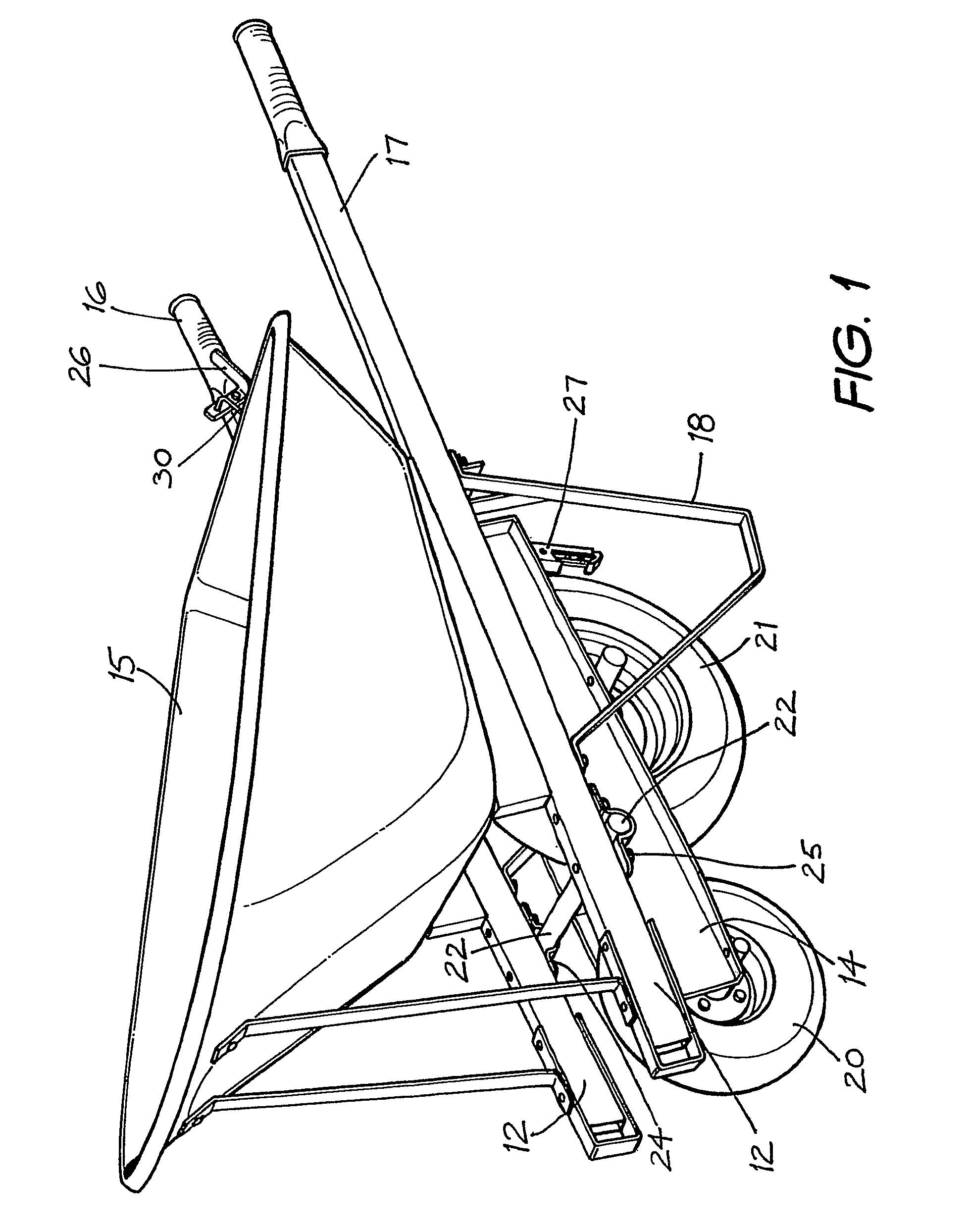
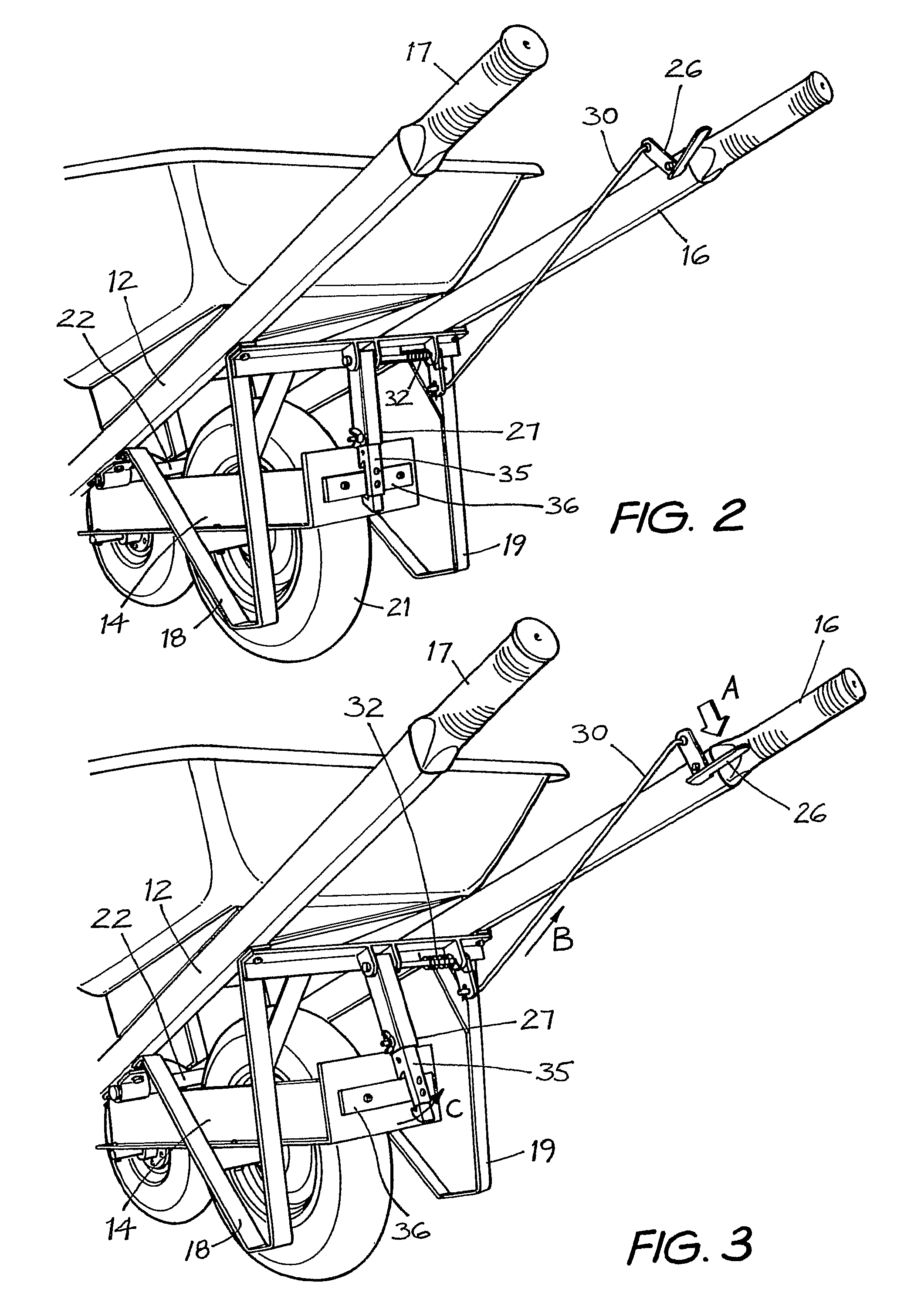
[0030]The wheelbarrow shown in FIGS. 1 to 10 has a frame, of which there is a top portion 12 and an undercarriage portion 14. There is an open topped vessel 15 mounted on the top portion 12 of the frame, and a pair of handle bars 16, 17 extending rearwardly and integrally from the top portion 12 of the frame. The wheelbarrow also includes a pair of ground engagable legs 18, 19. A first (or front) wheel 20 is connected to a front part of the undercarriage portion 14 of the frame. A second (or rear) wheel 21 is connected to a rear part of the undercarriage portion 14 of the frame. The second wheel 21 is rearwardly aligned with the first wheel 20.

[0031]Pivot axis means, in the form of a rod member 22 and a pair of clamp brackets 24, 25, interconnect the top and undercarriage portions 12, 14 and allow the top portion 12 of the frame to pivot relative to the undercarriage portion 14 of the frame.

[0032]There is a manually controllable linkage means that includes a finger operated trigger ...


PUM


Abstract

A wheelbarrow has a frame, having a top portion (12) and an undercarriage portion (14). There is an open topped vessel (15) mounted on the top portion (12) of the frame, and a pair of handle bars (16, 17) extending rearwardly and integrally from the top portion (12) of the frame. The wheelbarrow also has a pair of ground engagable legs (18, 19), and a front wheel (20) is connected to a front part of the undercarriage portion (14) of the frame, and a rear wheel (21) is connected to a rear part of the undercarriage portion (14) of the frame. The rear wheel (21) is aligned with the front wheel (20). There are pivot axis means (22, 24, 25) of the wheelbarrow for allowing the top portion (12) of the frame to pivot relative to the undercarriage portion (14) of the frame. Manually controllable linkage means (26,27,29,30,31,32) are also provided which are adjustable between first and second positions for allowing a user to link the top and undercarriage portions (12, 14) of the frame when in a first position so that they are unable to pivot relative to each other about the pivot axis means, and for allowing a user to unlink the top and undercarriage portions (12, 14) of the frame when in a second position so that they are able to pivot relative to each other about the pivot axis means.

Description

FIELD OF THE INVENTION[0001]The present invention relates to wheelbarrows and, in particular, to a two-wheeled wheelbarrow that is easier to tip and manoeuvre than conventional wheelbarrows.BACKGROUND OF THE INVENTION[0002]Conventional wheelbarrows have a single front wheel and a pair of opposed rear legs for supporting and maintaining upright balance of the wheelbarrow when it is not being lifted for movement. When these wheelbarrows carry a heavy load, they require considerable strength of the user to tip the wheelbarrow forward by pivotal motion about its front wheel.SUMMARY OF THE INVENTION[0003]It is an object of the present invention to provide a wheelbarrow that overcomes, or substantially ameliorates, the aforementioned shortcomings of the prior art, or at least provides a useful alternative.[0004]According to the invention, there is provided a wheelbarrow comprising:[0005](a) a frame, having a top portion and an undercarriage portion,[0006](b) an open topped vessel mounted ...

Claims


Application Information

Patent Timeline
Patent Type & Authority Patents(United States)
IPC IPC(8): B62B1/24
CPCB62B1/18B62B1/24B62B3/009B62B3/08B62B1/186B62B5/02B62B2301/00
Inventor MORRIS, RICHARD J.
Owner MORRIS RICHARD J
Why Eureka
Try Eureka