
Computer housing

a computer and shell technology, applied in the field of housing, can solve the problems of reducing the efficiency of the inner space of the shell, so as to achieve the effect of reducing the disadvantage and/or obviating the disadvantag

Inactive Publication Date: 2009-06-16
GIGA BYTE TECH CO LTD
View PDF10 Cites 19 Cited by
  • Summary
  • Abstract
  • Description
  • Claims
  • Application Information

AI Technical Summary

Benefits of technology

[0007]The present invention is to mitigate and / or obviate the disadvantage of the conventional computer housing.
[0008]The primary objective of the present invention is to provide a computer housing, wherein the peripheral device is suspended in or detached from the inside of the shell by the support bracket to save the inner space of the shell, so that the inner space of the shell is employed efficiently to mount more peripheral devices.
[0009]Another objective of the present invention is to provide a computer housing, wherein when the support bracket is rotatable to the open position, the support bracket is entirely detached from the side opening of the shell, and the peripheral device is entirely detached from the inside of the shell, so that the inner space of the shell is entirely exposed outwardly, thereby facilitating assembly, disassembly and maintenance of the parts contained in the inner space of the shell.
[0010]A further objective of the present invention is to provide a computer housing, wherein the support bracket is mounted onto and detached from the connecting seat easily, quickly and conveniently without needing aid of additional tools, thereby facilitating the user assembling and disassembling the support bracket.
[0011]A further objective of the present invention is to provide a computer housing, wherein the support bracket is positioned by the catch member so that the support bracket will not fall down due to hit to prevent the user from being hurt and to prevent the peripheral device from being damaged.

Problems solved by technology

However, the inner space of the shell is not used efficiently.
In addition, the top cover cannot be detached, so that the top cover is easily returned to the original state due to unintentional touch or hit, thereby causing danger to the user when repairing the computer housing.
However, the inner space of the shell is not used efficiently.
In addition, the rotation case cannot be detached and well supported, so that the rotation case is easily returned to the original state due to unintentional touch or hit, thereby causing danger to the user when repairing the computer housing.

Method used


Image

  • Computer housing
  • Computer housing
  • Computer housing

Examples


Embodiment Construction

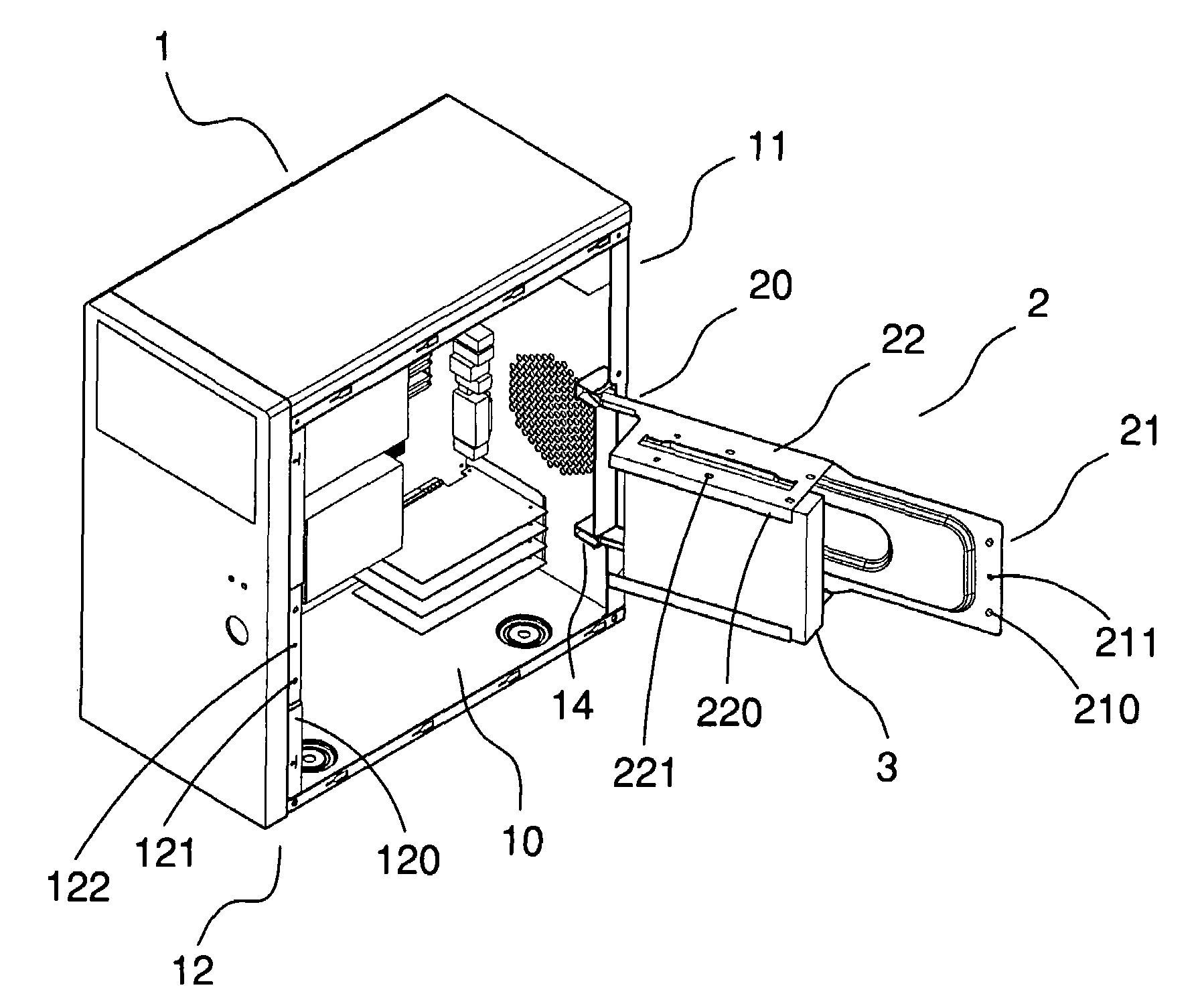
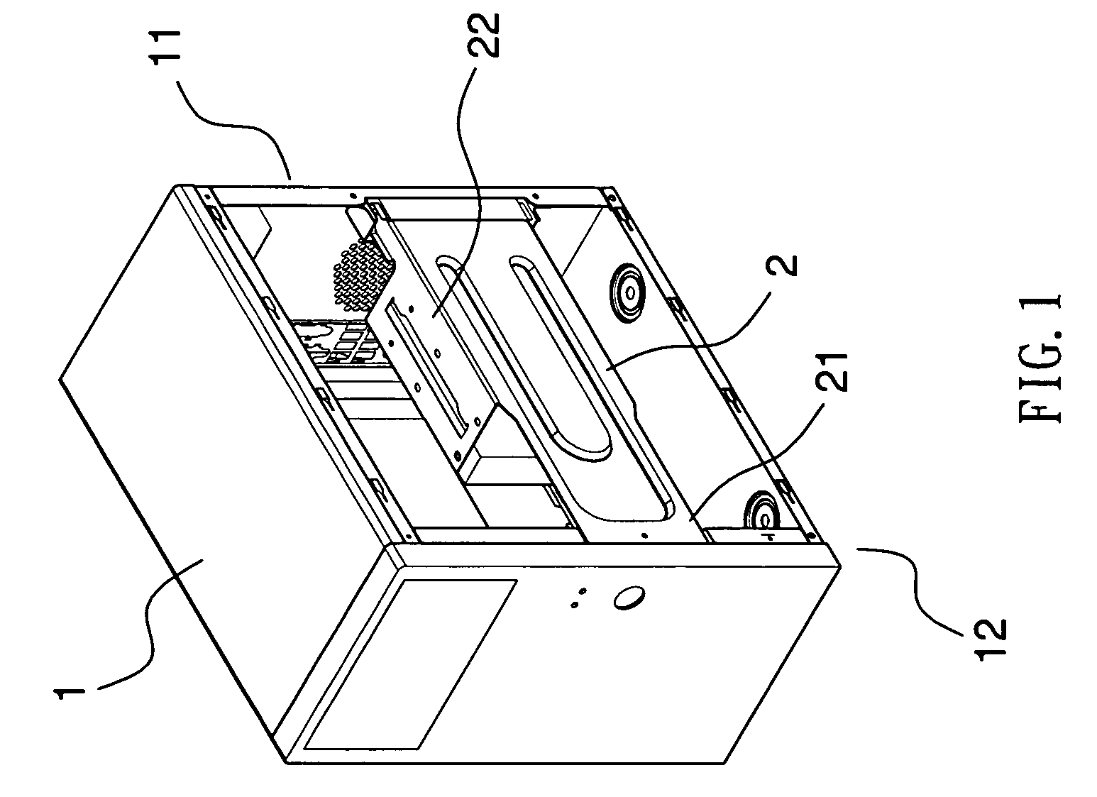
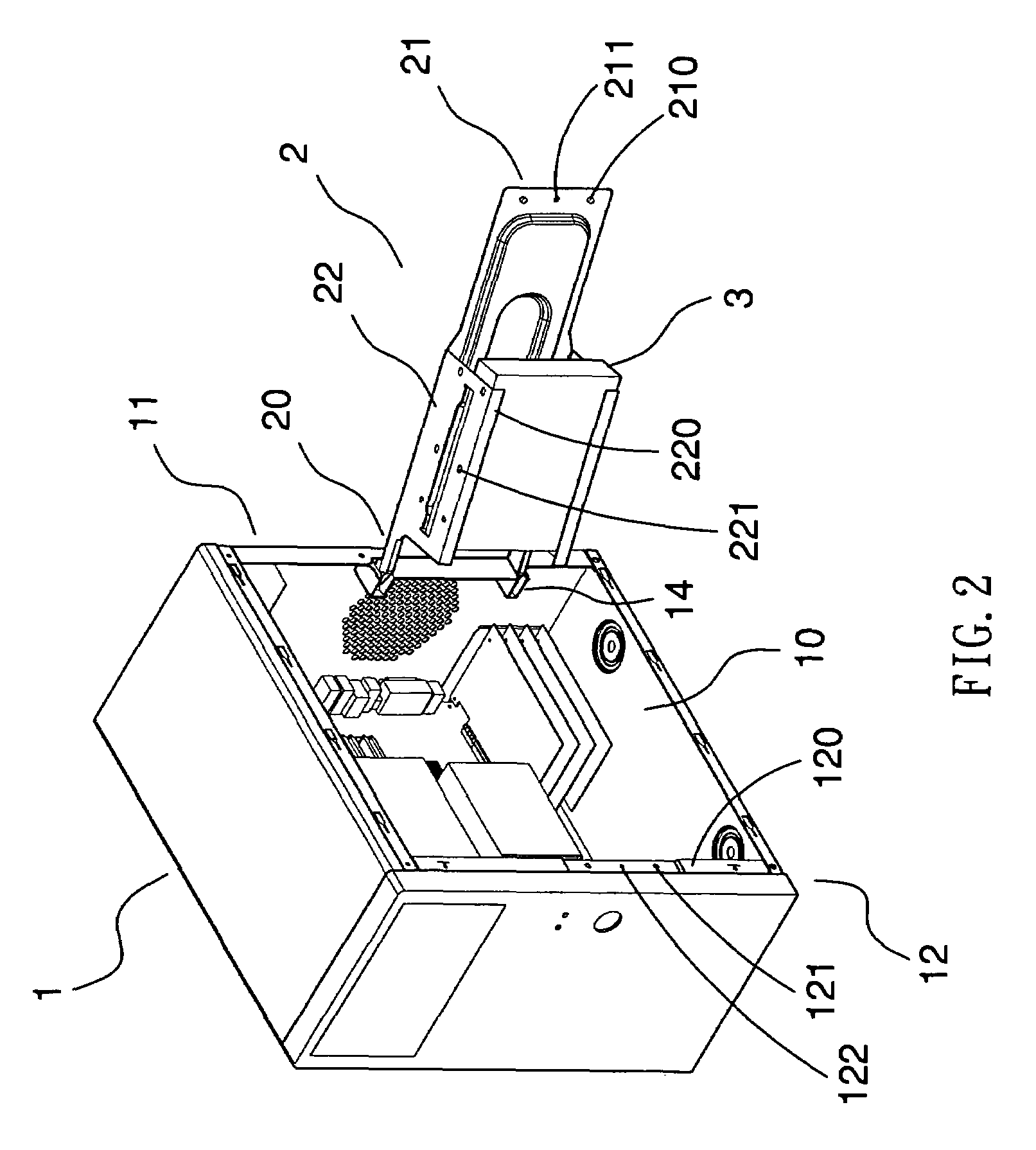
[0027]Referring to the drawings and initially to FIGS. 1-4, a computer housing in accordance with the preferred embodiment of the present invention comprises a shell 1, and a support bracket 2 rotatably mounted on the shell 1.

[0028]The shell 1 has a side opening 10, a first side wall 11 and a second side wall 12. The first side wall 11 and the second side wall 12 of the shell 1 are located at two opposite sides of the side opening 10.

[0029]The support bracket 2 has a head portion 20 rotatably mounted on the first side wall 11 of the shell 1, a tail portion 21 extending to the second side wall 12 of the shell 1, and a support portion 22 located between the head portion 20 and the tail portion 21 for mounting a peripheral device 3 (hard disk, floppy disk, optical disk, CD burner and the like). Preferably, the peripheral device 3 is a hard disk.

[0030]When the support bracket 2 is rotatable to an open position as shown in FIG. 2, the tail portion 21 of the support bracket 2 is detached ...


PUM


Abstract

A computer housing includes a shell having a side opening, a first side wall and a second side wall, and a support bracket rotatably mounted on the shell and having a head portion, a tail portion, and a support portion. Thus, when the support bracket is rotatable to a closed position, the tail portion of the support bracket is rested on the second side wall of the shell, and the support portion of the support bracket is received in an inside of the shell, and when the support bracket is rotatable to an open position, the tail portion of the support bracket is detached from the second side wall of the shell, and the support portion of the support bracket is detached from the inside of the shell.

Description

BACKGROUND OF THE INVENTION[0001]1. Field of the Invention[0002]The present invention relates to a housing, and more particularly to a computer housing for the main frame of a computer.[0003]2. Description of the Related Art[0004]A conventional computer housing comprises a shell, a rotatable top cover rotatably mounted in the shell, and a screw board fixed on the top cover for mounting a peripheral device (hard disk, floppy disk, optical disk, CD burner and the like). However, the inner space of the shell is not used efficiently. In addition, the top cover cannot be detached, so that the top cover is easily returned to the original state due to unintentional touch or hit, thereby causing danger to the user when repairing the computer housing.[0005]Another conventional computer housing comprises a shell, a seat mounted in the shell, and a rotation case rotatably mounted on the seat for mounting a peripheral device (hard disk, floppy disk, optical disk, CD burner and the like). Howeve...

Claims


Application Information

Patent Timeline
Patent Type & Authority Patents(United States)
IPC IPC(8): H05K5/00G06F1/16H05K7/00
CPCG06F1/181G06F1/187
Inventor LIN, WEN-HAOLEE, WEI-JEN
Owner GIGA BYTE TECH CO LTD
Learn More