Effective deployment of temporal noise shaping (TNS) filters

a temporal noise shaping and filter technology, applied in the field can solve the problems of ineffective deployment of tns filter for most audio signals, adverse effect of reconstructed signal audible artifacts, and frequency spectra not covered by tns filter receiving the beneficial masking effect of tns, etc., and achieve the effect of effective deployment of tns filter

Inactive Publication Date: 2009-06-16
FRAUNHOFER GESELLSCHAFT ZUR FOERDERUNG DER ANGEWANDTEN FORSCHUNG EV
View PDF22 Cites 8 Cited by
  • Summary
  • Abstract
  • Description
  • Claims
  • Application Information

AI Technical Summary

Problems solved by technology

In cases where the need for additional filters remains but the limit of permissible filters has been reached, the frequency spectra not covered by a TNS filter do not receive the beneficial masking effects of TNS.
This current practice is not an effective way of deploying TNS filters for most audio signals.
This results in part of the spectrum (e.g., b4 through b8) not being covered by TNS filters, with the adverse effect that audible artifacts may appear in the reconstructed signal.

Method used


Image

  • Effective deployment of temporal noise shaping (TNS) filters
  • Effective deployment of temporal noise shaping (TNS) filters
  • Effective deployment of temporal noise shaping (TNS) filters

Examples


Embodiment Construction

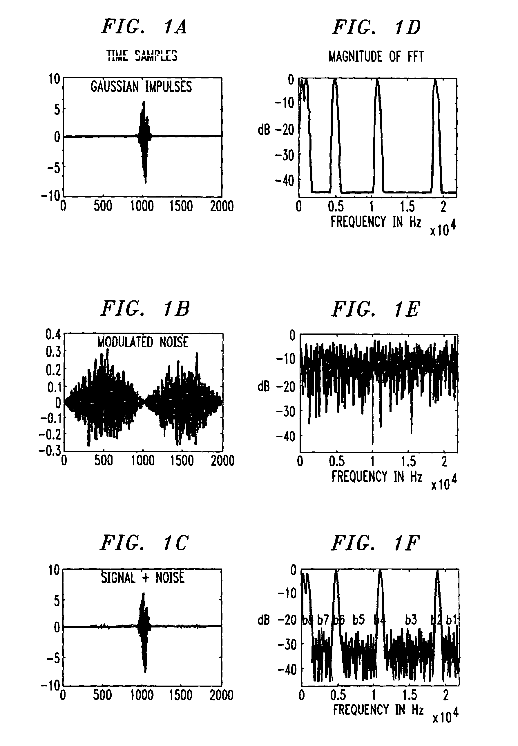
[0024]Referring now to the drawings, as previously discussed, FIGS. 1A-1C illustrate an audio signal, a noise signal, and a superposition of these two signals within a block, respectively. The frequency spectra of each signal is illustrated in FIGS. 1D-1F. From FIG. 1F, it can be seen that the signal shown in FIG. 1A is audible in the set of frequency bands including b2, b4, b6 and b8. In contrast, the signal shown in FIG. 1B is audible in bands covering b1, b3, b5 and b7. In order for the entire spectra of the block to be covered by TNS filters, the current method of TNS filter deployment would require eight filters—one for each of the frequency bands 1 through 8, which, as discussed above, is not permitted by the current AAC standard.

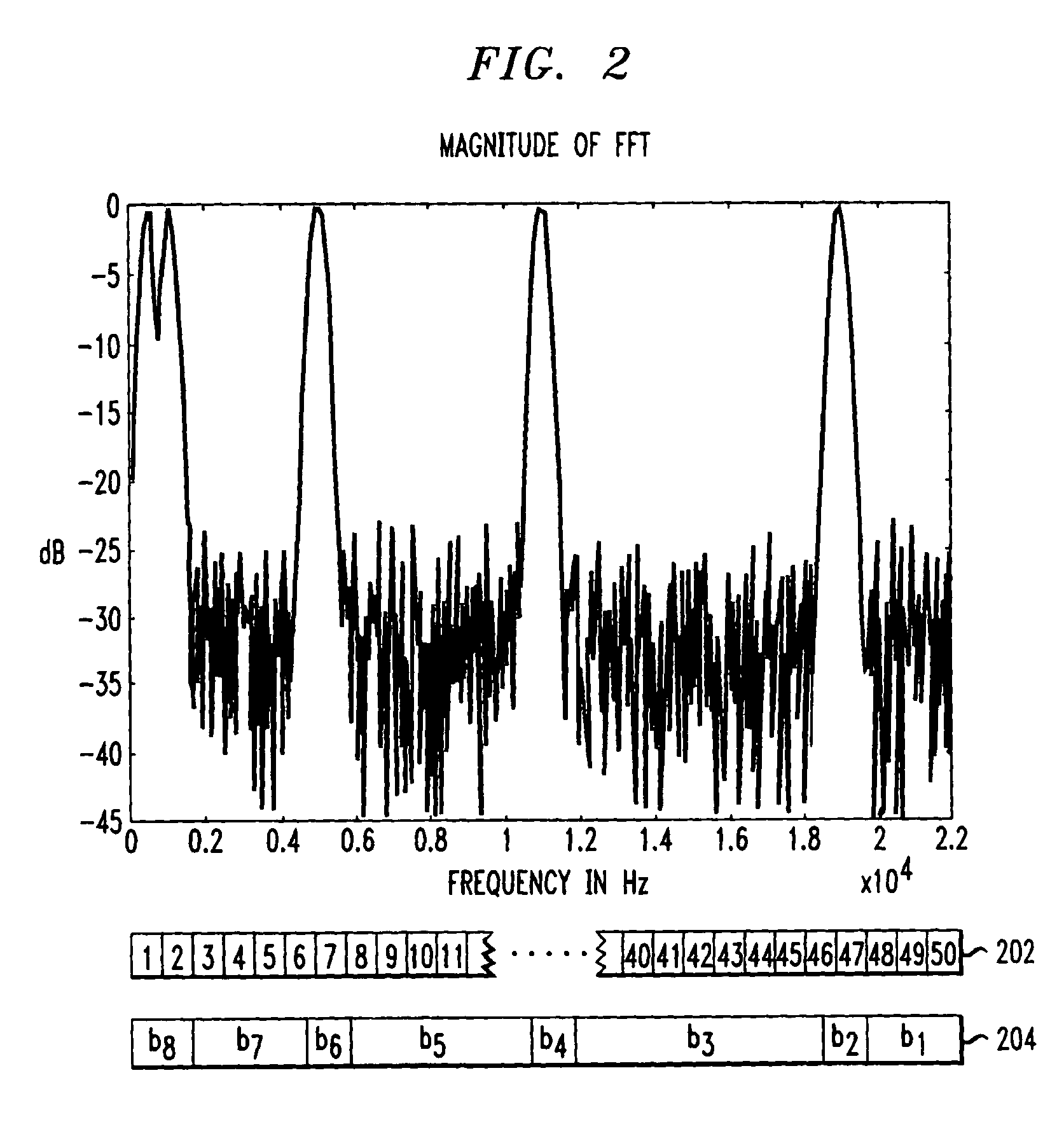
[0025]FIG. 2 is essentially FIG. 1F enlarged to illustrate how the boundaries of frequency bands such as b1 through b8 are defined in accordance with one aspect of the present invention. As indicated by reference numeral 202, the frequency range of th...


PUM


Abstract

In the MPEG2 Advanced Audio Coder (AAC) standard, Temporal Noise Shaping (TNS) is currently implemented by defining one filter for a given frequency band, and then switching to another filter for the adjacent frequency band when the signal structure in the adjacent band is different than the one in the previous band. The AAC standard limits the number of filters used to either one filter for a “short” block or three filters for a “long” block. In cases where the need for additional filters is present but the limit of permissible filters has been reached, the remaining frequency spectra are simply not covered by TNS. This current practice is not an effective way of deploying TNS filters for most audio signals. We propose two solutions to deploy TNS filters in order to get the entire spectrum of the signal into TNS. The first method involves a filter bridging technique and complies with the current AAC standard. The second method involves a filter clustering technique. Although the second method is both more efficient and accurate in capturing the temporal structure of the time signal, it is not AAC standard compliant. Thus, a new syntax for packing filter information derived using the second method for transmission to a receiver is also outlined.

Description

[0001]This application is a continuation application of U.S. patent application Ser. No. 09 / 537,948, filed on Mar. 29, 2000 now U.S. Pat. No. 7,099,830, and incorporated by reference herein in its entirety.FIELD OF THE INVENTION[0002]This invention relates generally to TNS filter signal processing and, more particularly, to the effective deployment of TNS filters.BACKGROUND[0003]Temporal Noise Shaping (TNS) has been successfully applied to audio coding by using the duality of linear prediction of time signals. (ee, J. Herre and J. D. Johnston, “Enhancing the Performance of Perceptual Audio Coding by Using Temporal Noise Shaping (TNS),” in 101st AES Convention, Los Angeles, November 1996, a copy of which is incorporated herein by reference). As is well known in the art, TNS uses open-loop linear prediction in the frequency domain instead of the time domain. This predictive encoding / decoding process over frequency effectively adapts the temporal structure of the quantization noise to ...

Claims


Application Information

Patent Timeline
Patent Type & Authority Patents(United States)
IPC IPC(8): G06F17/00G06F17/10G10L19/00G10L19/14
CPCG10L19/03
Inventor JOHNSTON, JAMES DAVIDKUO, SHYH-SHIAW
Owner FRAUNHOFER GESELLSCHAFT ZUR FOERDERUNG DER ANGEWANDTEN FORSCHUNG EV
Why Eureka
Try Eureka