
Piezoelectric inkjet printhead having a unidirectional shutter

a piezoelectric inkjet and printhead technology, applied in printing and other directions, can solve the problems of increasing the cpi of the printhead, slow printing speed of the conventional inkjet printhead, and reducing the distance dn between the adjacent nozzles, so as to restrict the backflow of ink

Inactive Publication Date: 2009-06-23
SAMSUNG ELECTRO MECHANICS CO LTD
View PDF10 Cites 0 Cited by
  • Summary
  • Abstract
  • Description
  • Claims
  • Application Information

AI Technical Summary

Benefits of technology

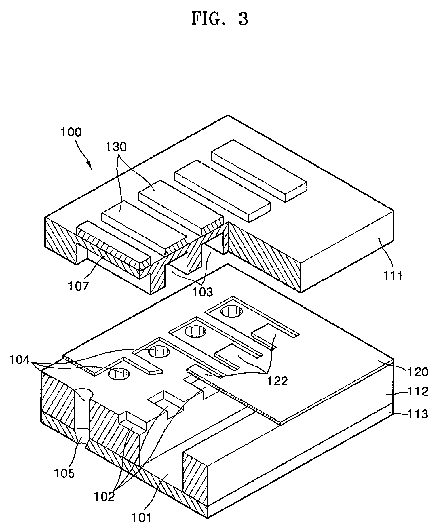
The present invention provides an inkjet printhead with a unidirectional shutter that overcomes the limitations and disadvantages of related art. The printhead includes a plurality of layers, including an ink manifold, pressure chambers, piezoelectric actuators, ink ejector nozzles, and shutters. Each shutter is flexible and adapted to reversibly restrict ink flow from its corresponding pressure chamber in response to the driving force. The shutter has a thin plate shape and may be made of metal or elastomer. The printhead may have a plurality of ink ejector nozzles arrayed along its length, and each pressure chamber communicates to the ink passage via one of its corresponding ink flow paths. The technical effects of the invention include improved ink ejection, reduced backflow of ink, and improved print quality.

Problems solved by technology

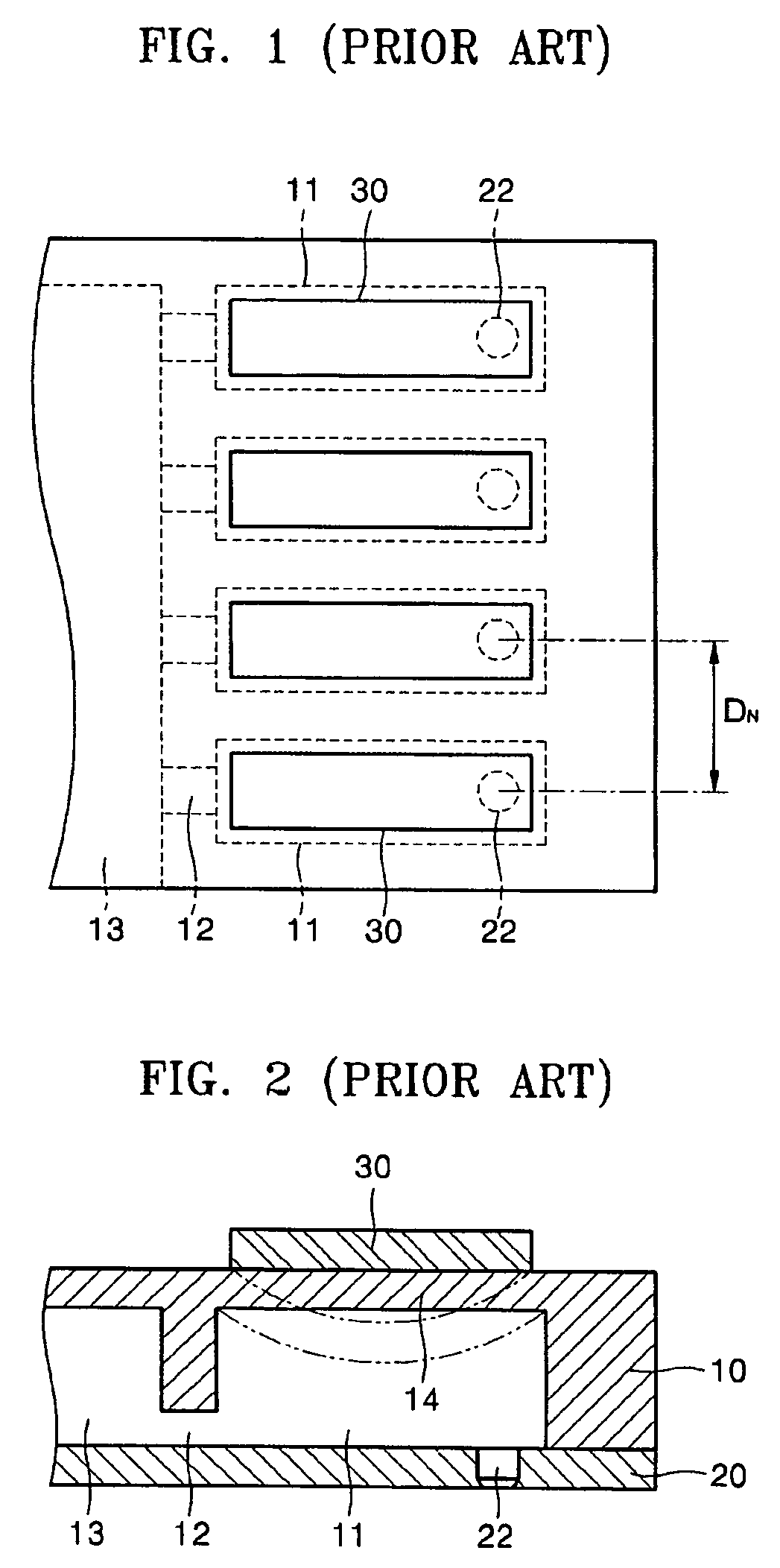
However, the conventional piezoelectric inkjet printhead having the structure described above has limitations in reducing the distance DN between the adjacent nozzles 22, for the previously mentioned reasons.
Thus, increasing the CPI of the printhead may be at odds with maintaining a desired volume of ink displacement.
Accordingly, the conventional inkjet printhead has a slow printing speed, due to the need to move the printhead across the width of the sheet before advancing the sheet.
However, it is not straightforward to increase the CPI to match the desired DPI of an image.
Since the conventional piezoelectric inkjet printhead has structural limitations in increasing the number of CPI for the reasons described above, it is difficult to have the same number of CPI as the number of DPI of the image.

Method used


Image

  • Piezoelectric inkjet printhead having a unidirectional shutter
  • Piezoelectric inkjet printhead having a unidirectional shutter
  • Piezoelectric inkjet printhead having a unidirectional shutter

Examples


Embodiment Construction

[0034]Korean Patent Application No. 10-2004-0089212, filed on Nov. 4, 2004, in the Korean Intellectual Property Office, and entitled: “Piezoelectric Inkjet Printhead Having a Unidirectional Shutter,” is incorporated by reference herein in its entirety.

[0035]The present invention will now be described more fully hereinafter with reference to the accompanying drawings, in which exemplary embodiments of the invention are shown. The invention may, however, be embodied in different forms and should not be construed as limited to the embodiments set forth herein. Rather, these embodiments are provided so that this disclosure will be thorough and complete, and will fully convey the scope of the invention to those skilled in the art. In the figures, the dimensions of layers and regions may be exaggerated for clarity of illustration. It will also be understood that when a layer is referred to as being “on” another layer or substrate, it can be directly on the other layer or substrate, or int...


PUM


Abstract

A piezoelectric inkjet printhead including a reversible shutter disposed in an ink flow path is disclosed. The inkjet printhead may includes a plurality of ink pressure chambers, a plurality of piezoelectric actuators to provide the plurality of ink pressure chambers with a driving force for ink ejection, an ink manifold to supply the plurality of pressure chambers, a plurality of restrictors disposed in the ink flow path between the manifold and the plurality of pressure chambers, a plurality of ink ejecting nozzles coupled to the plurality of pressure chambers, and a plurality of unidirectional shutters. The shutters may be disposed at respective outlets of the plurality of restrictors and may be adapted to open the restrictor when ink is supplied from the restrictor to the pressure chamber and close the restrictor and restrict or prevent the backflow of ink when ink is ejected from the pressure chamber through the nozzle.

Description

BACKGROUND OF THE INVENTION[0001]1. Field of the Invention[0002]The present invention relates to an inkjet printhead. More particularly, the present invention relates to a piezoelectric inkjet printhead that can reduce a volume of a pressure chamber to increase a number of channels per inch (CPI).[0003]2. Description of the Related Art[0004]In general, inkjet printheads are devices for printing a predetermined color image by ejecting a small volume of droplet of printing ink at a desired position on a print medium, such as a sheet of paper or a fabric. Inkjet printheads are largely categorized into two types, depending on the ink ejection mechanism used. A first type is a thermal inkjet printhead, in which a heat source is employed to form and expand bubbles in ink, causing ink droplets to be ejected. A second type is a piezoelectric inkjet printhead, in which a piezoelectric element is deformed to exert pressure on ink, causing ink droplets to be ejected.[0005]A conventional piezoe...

Claims


Application Information

Patent Timeline
Patent Type & Authority Patents(United States)
IPC IPC(8): B41J2/045
CPCB41J2/055B41J2/14233B41J2002/14193B41J2/045
Inventor KWON, KYE-SIKIM, SEONG-JINSHIN, SEUNG-JOOSUNG, GEE-YOUNGKUK, KEONSONG, MI-JEONG
Owner SAMSUNG ELECTRO MECHANICS CO LTD
Learn More