
Visual stimulator

a technology of visual stimulators and stimulators, applied in the field of visual stimulators, can solve problems such as corresponding erg-potentials

Inactive Publication Date: 2009-06-23
ANTTI VALJAKKA
View PDF8 Cites 2 Cited by
  • Summary
  • Abstract
  • Description
  • Claims
  • Application Information

AI Technical Summary

Benefits of technology

Enables the registration of ERG responses and other biopotentials from freely moving subjects by ensuring consistent light stimulus delivery and excluding non-light factors, allowing for precise measurement of visual dynamics and chromatic characteristics.

Problems solved by technology

The measuring of ERG-potentials corresponding with the magnitude of visual stimulus from a laboratory animal or a human moving freely creates a technical problem because in free motion the direction of gaze in 3-dimensional space as well as the place of the body or a part of it such as the head continuously changes between different measurements.
Another common technical problem while applying some visual stimulus sources, such as a flashlight, are other physical effects created by them than the changes in light intensity, which other physical effects may be the change in magnetic field and sound, among other things.

Method used


Image

  • Visual stimulator
  • Visual stimulator
  • Visual stimulator

Examples


Embodiment Construction

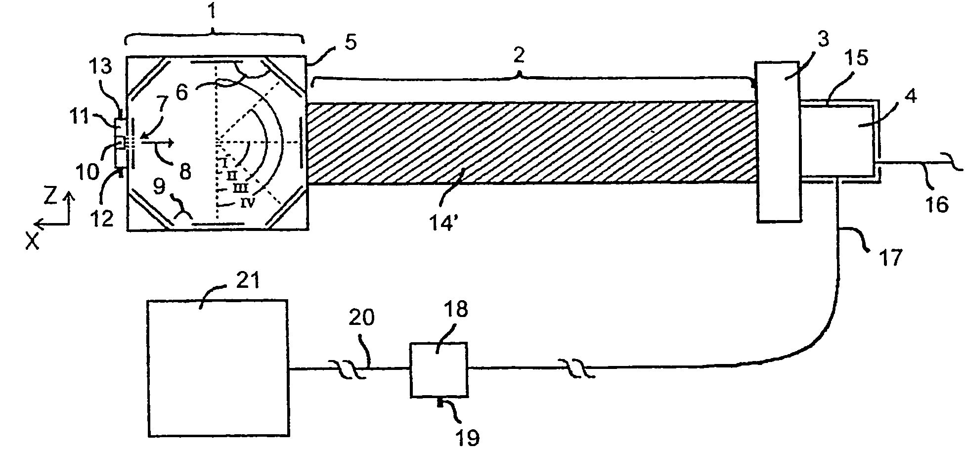
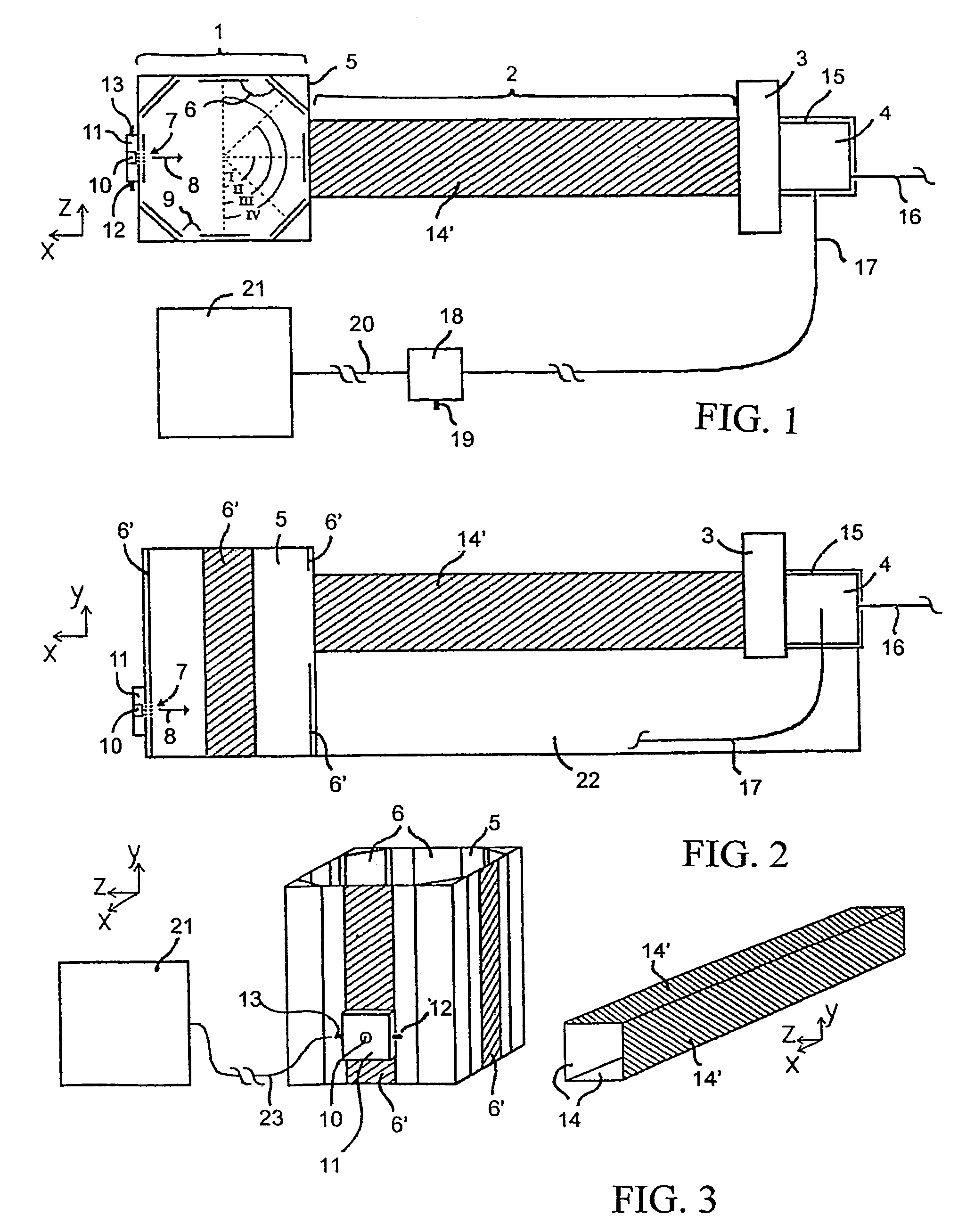
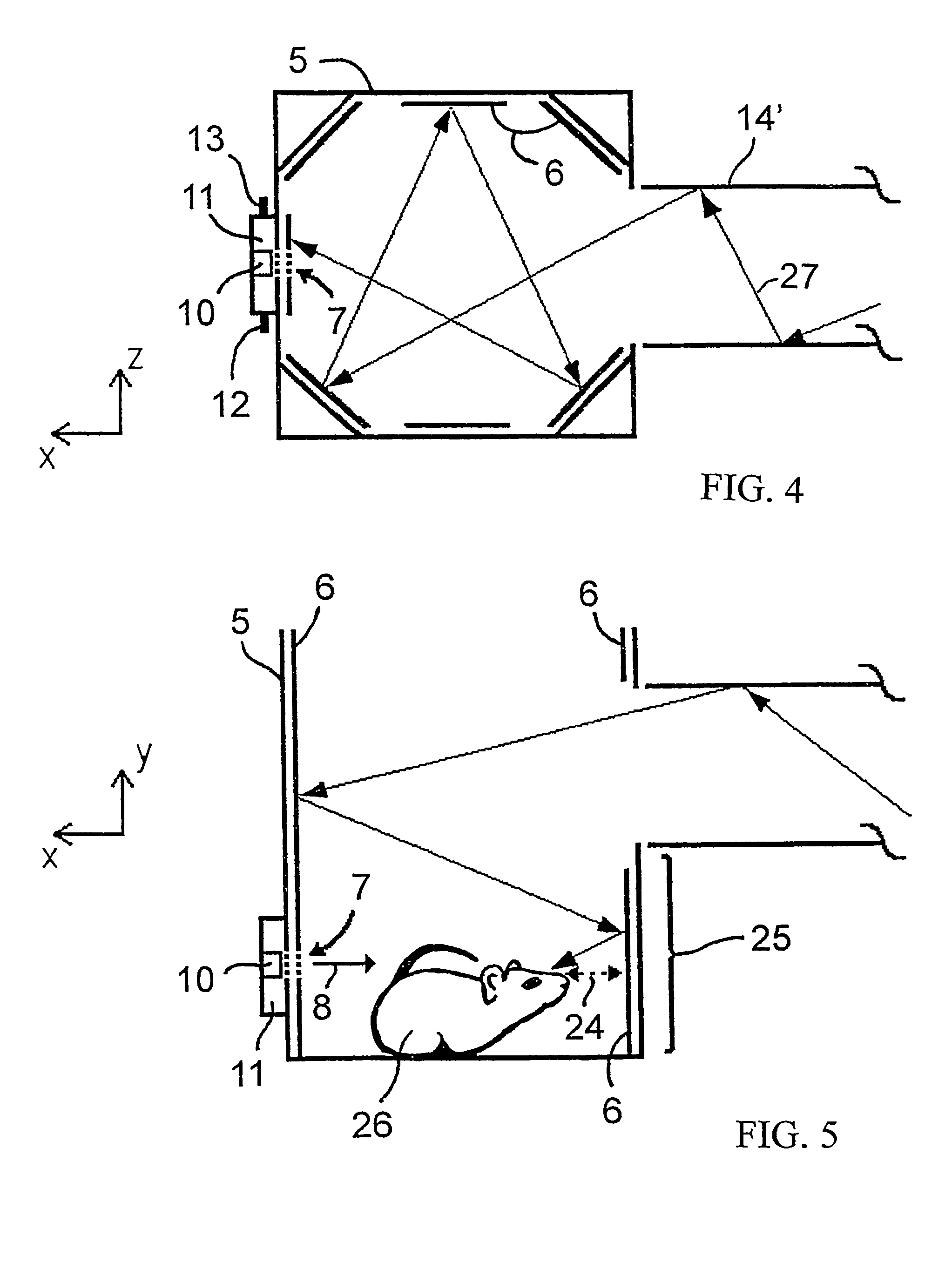
[0006]The visual stimulator in accordance with the invention comprises a mirror chamber and a mirror tube constructed of mirrors, in which chamber and tube the reflecting sites of the mirrors form various angles with respect to each other, and which sites have been connected to each other such that light beams are dispersed from the mirror tube to the mirror chamber without hindrance regardless of the location of the object or a part of an object to be examined in the mirror chamber, and to the other end of the mirror tube, as seen away from the mirror chamber, a light stimulating source has been aligned.

[0007]The above mentioned purposes are achieved by applying a visual stimulator in accordance with the invention, which stimulator comprises a mirror chamber and a mirror tube, which have been connected to each other such that while a laboratory animal to be examined, or some other biological object such as the head of a human has been placed in the mirror chamber light beams are di...


PUM


Abstract

The present invention relates to a visual stimulator, which comprises a light stimulation source, a regulable attenuator of light, mirrors for reflecting light and light detectors. The visual stimulator in accordance with the invention comprises a mirror chamber and a mirror tube constructed of mirrors in which the reflecting points of the mirrors form various angles with respect to each other, and which have been connected to each other such that light beams disperse from the mirror tube to the mirror chamber without hindrance regardless of the location of the object to be examined or a part of it in the mirror chamber and though the location of the object or a part of it would vary in certain limits in the mirror chamber, and that to one end of the mirror tube, viewed away from the mirror chamber a light stimulation source has been directed.

Description

CROSS REFERENCE TO RELATED APPLICATION[0001]This application is a continuation of International Patent Application No. PCT / FI03 / 00351 filed May 5, 2003.[0002]The present invention relates to a visual stimulator, which comprises a light stimulation source, a regulable attenuator of light, mirrors for reflecting light and light detectors.BACKGROUND OF THE INVENTION[0003]There are two technical requirements in stimulating techniques applied in visual measurement methods for creating a visual response: the way the visual stimulus has been pointed to the eye and the way other factors of the stimulus source than factors of light effect have been eliminated from the object for measurement. In visual measurement methods based on recognized techniques which have been designed for measuring the physiological potential change of retina of the eye (electroretinogram, ERG) for a visual stimulus carried out on test animals has been represented that by applying mirrors, lenses or a LED-light sourc...

Claims


Application Information

Patent Timeline
Patent Type & Authority Patents(United States)
IPC IPC(8): A61B3/10A61B3/02A61B3/032A61B5/0496
CPCA61B3/0091A61B5/0496A61B3/032A61B5/398
Inventor VALJAKKA, ANTTIURTTI, ARTOAHONEN, JANNE
Owner ANTTI VALJAKKA
Learn More