Fluid bearing and method of operation

a technology of fluid bearings and bearings, applied in the direction of bearings, shafts and bearings, positive displacement liquid engines, etc., can solve the problems of fluid loss, damage to one or both surfaces, fluid loss, etc., to control friction and wear of bearings, control separation force, and effectively vary the active hydrostatic area

Inactive Publication Date: 2009-06-30
GOVERNMENT OF THE US REPRESENTED BY THE ADMINISTRATOR OF THE U S ENVIRONMENTAL PROTECTION AGENCY
View PDF32 Cites 6 Cited by
  • Summary
  • Abstract
  • Description
  • Claims
  • Application Information

AI Technical Summary

Benefits of technology

[0020]Flow of pressurized fluid to the pads of the insert is controlled such that the bearing does not operate in full hydrostatic mode. Instead, a separating force generated by surface force of the fluid is controlled such that the force exerted on the bearing exceeds the separating force, although the fluid pressure is also controlled to selected pads to keep the separating force within a selected margin of the force exerted on the bearing, to control friction and wear of the bearing.
[0021]According to an embodiment, control of the separating force is achieved by selectively pressurizing individual hydrostatic pads, thereby effectively varying the active hydrostatic area of the bearing.

Problems solved by technology

If the surface force drops below the balance force, the rotor will make contact with the stator, possibly resulting in damage to one or both surfaces.
However, any excess supply pressure results in loss of fluid.
However, because of the limitations of hydrostatic bearings, there are problems associated with such use.
However, this means that when load levels drop, a significant overpressure will exist, resulting in loss of fluid.
While many of the proposed designs attempt to address this problem, they are, for the most part, impractical or ineffective.
While it has been thought desirable to employ fluid bearings with pump / motors of this kind in order to improve efficiency and reduce wear, it has been found problematic, due to the complex nature of the changes in force and vector at play in these systems.
Because of these extreme conditions, little success has been shown using fluid bearings.

Method used


Image

  • Fluid bearing and method of operation
  • Fluid bearing and method of operation
  • Fluid bearing and method of operation

Examples


Embodiment Construction

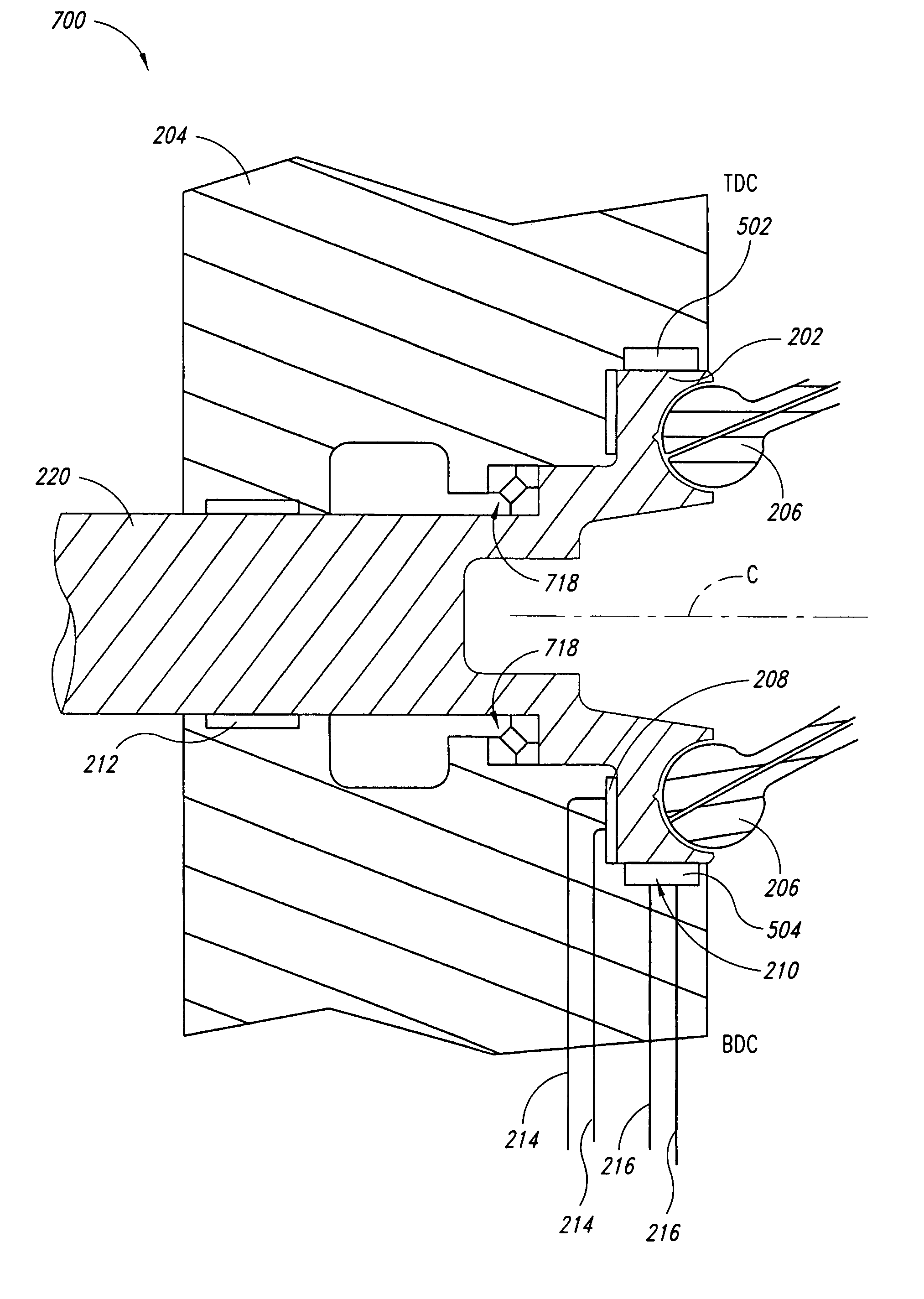
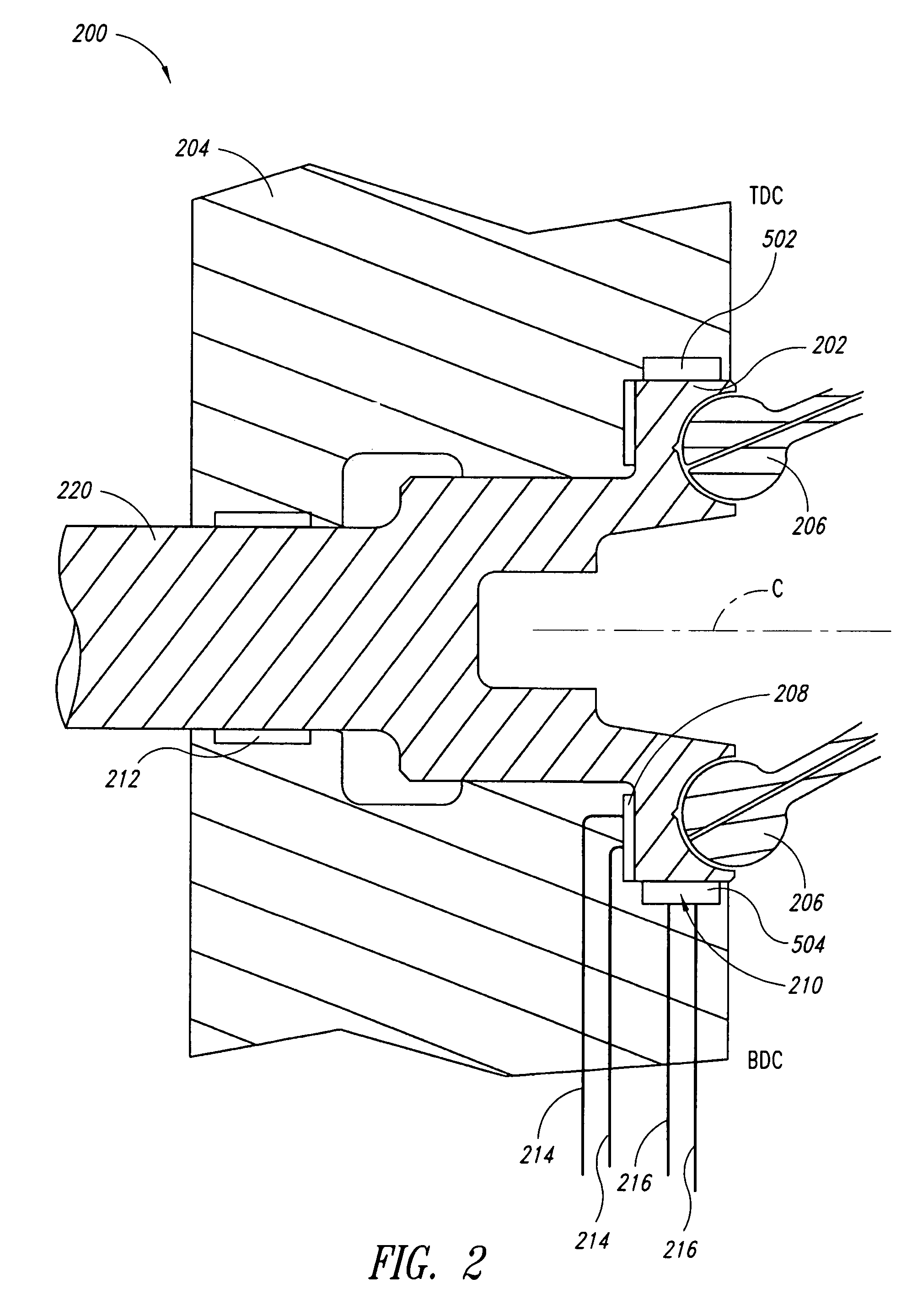
[0030]Various embodiments of the invention will now be described with reference to FIGS. 2-6. For the purpose of the disclosure and claims, the term fluid pressure will be used to refer to pressure of a fluid relative to area, such as, for example, psi. The term surface force will be used to refer to hydrostatic force exerted on an opposing surface, which is a function of the fluid pressure multiplied by the total surface area of pressurized fluid in contact with the opposing surface. Separating force refers to the force exerted by the surface force to separate elements. The term balance force will be used to refer to a hydrostatic force at which the surface force exerts a force equal to an opposing force exerted by an opposing surface. Either of the terms “motor” and “pump / motor” may be considered to read on a hydraulic motor, pump, or pump / motor.

[0031]The term axial force is used herein to refer to force vectors that lie substantially parallel to an axis of rotation of a motor's d...


PUM


Abstract

A fluid bearing includes hydrostatic pads formed in a surface and positioned to exert a separating force, and a land formed on the surface of the insert and configured to act as a bushing to allow rotation while the first and second pads are pressurized at less than a hydrostatic balance force. Pressurized fluid to the pads of the insert is controlled to prevent operation in full hydrostatic mode. More particularly, a separating force generated by surface force of the pads is controlled such that the separating force does not exceed a force exerted on the bearing. The fluid pressure is also controlled to keep the separating force within a selected margin of the force exerted on the bearing, to control wear of the bearing. Control of the separating force is achieved by selectively pressurizing individual hydrostatic pads, thereby effectively varying the active hydrostatic area of the bearing.

Description

BACKGROUND OF THE INVENTION[0001]1. Field of the Invention[0002]The present disclosure relates generally to thrust and journal bearings, and in particular, to hydrostatic bearings.[0003]2. Description of the Related Art[0004]Fluid bearings are bearings that operate with a layer of fluid, such as a gas or a liquid, between moving parts. In comparison to conventional bearings such as roller bearings or ball bearings, for example, fluid bearings provide significant reduction in friction and wear. One common type of fluid bearing is the hydrostatic bearing, in which a rotor element is supported by a fluid to rotate relative to a stator element. Typically, the bearing is provided with a fluid supply under pressure to one or more cavities, sometimes referred to as pads, which are commonly formed in a stator element, between the rotor and stator elements. When the total surface force in the cavities balances the downward force of the rotor element, the element lifts off the surface of the ...

Claims


Application Information

Patent Timeline
Patent Type & Authority Patents(United States)
IPC IPC(8): F16C32/06
CPCF04B1/2085F16C32/0696F16C2360/00
Inventor GRAY, JR., CHARLES L.
Owner GOVERNMENT OF THE US REPRESENTED BY THE ADMINISTRATOR OF THE U S ENVIRONMENTAL PROTECTION AGENCY
Why Eureka
Try Eureka