Edge grinding device for judging optical center through light refraction

A laser device and edging technology, applied in the field of optical lenses, can solve the problems of the lens being clamped on the roller, not in the physical center, and the lens being damaged.

Inactive Publication Date: 2021-02-19
蓝迟高
View PDF0 Cites 0 Cited by
  • Summary
  • Abstract
  • Description
  • Claims
  • Application Information

AI Technical Summary

Problems solved by technology

[0003] In the prior art, during the edging process of the optical lens, the friction block and the lens are contacted and rubbed, and the lens is moved by the thrust of the friction block. The clamping force and the adsorption force are not large enough to cause displacement, and the suction and adsorption are always carried out, resulting in waste of resources. , the optical center of the lens is not at the physical center, and the lens cannot be clamped on the roller with the naked eye. When the optical center and the physical center are not at the same place, it is impossible to judge to stop the machine and completely save the lens that could have been saved. damage, so a edging device that uses the refraction of light to judge the optical center came into being

Method used


Image

  • Edge grinding device for judging optical center through light refraction
  • Edge grinding device for judging optical center through light refraction
  • Edge grinding device for judging optical center through light refraction

Examples


Embodiment Construction

[0020] The following will clearly and completely describe the technical solutions in the embodiments of the present invention with reference to the accompanying drawings in the embodiments of the present invention. Obviously, the described embodiments are only some, not all, embodiments of the present invention. Based on the embodiments of the present invention, all other embodiments obtained by persons of ordinary skill in the art without making creative efforts belong to the protection scope of the present invention.

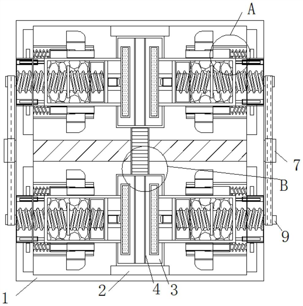
[0021] see Figure 1-5 , a kind of edging device that utilizes the refraction of light to determine the optical center, including a body 1, the upper and lower inner walls of the body 1 are fixedly connected with a base 2, and the end of the base 2 away from the body 1 is fixedly connected with a friction block 3, and the optics of the lens initially The center is located at the physical center, the brush 4 ensures that the center of the lens is at the same le...


PUM


Abstract

The invention relates to the technical field of optical lenses, and provides an edge grinding device for judging an optical center through light refraction. The edge grinding device comprises a machine body; bases are fixedly connected to the upper and lower inner walls of the machine body; friction blocks are fixedly connected to the ends, away from the machine body, of the bases; brushes are arranged on the outer walls of the friction blocks, and rack plates are fixedly connected to the outer walls of the friction blocks; and the outer walls of the rack plates are movably connected with gears. According to the edge grinding device for judging the optical center through the light refraction provided by the invention, lubricating oil is not prone to being mixed into air, a movable block, adrainage block and an adsorber are in complete contact, the drainage block moves to form a vacuum environment, the suction force of the adsorber to a lens is increased, a threaded column drives a second rotating shaft to rotate while rotating, the second rotating shaft drives a belt to rotate, the belt drives a first rotating shaft to rotate, the first rotating shaft drives the gears to rotate, the gears drive the rack plates to move, and the adsorber adsorbs the lens to rotate to be in contact with the friction blocks to prevent lens deviation during friction.

Description

technical field [0001] The invention relates to the technical field of optical lenses, in particular to an edge grinding device for judging the optical center by using the refraction of light. Background technique [0002] Optical lens is a kind of lens made of optical glass, which has specific requirements for optical properties such as refractive index, dispersion, transmittance, spectral transmittance and light absorption. Optical lens is often used in cameras, glasses and microscopes. With the development of the times, the The requirements for optical lenses are getting higher and higher, and the processing of optical lenses is getting better and better. Processing optical lenses requires that the optical center be at the physical center. [0003] In the prior art, during the edging process of the optical lens, the friction block and the lens are contacted and rubbed, and the lens is moved by the thrust of the friction block. The clamping force and the adsorption force a...

Claims


Application Information

Patent Timeline
Patent Type & Authority Applications(China)
IPC IPC(8): B24B9/14B24B41/06B24B41/02B24B55/00B24B49/12B24B47/12
CPCB24B9/14B24B9/146B24B41/02B24B41/06B24B47/12B24B49/12B24B55/00
Inventor 蓝迟高
Owner 蓝迟高
Why Eureka
Try Eureka