
Discharge valve assembly of reciprocating compressor

a compressor and valve assembly technology, applied in the direction of positive displacement liquid engines, piston pumps, liquid fuel engines, etc., can solve the problems of overcompression-related loss, large valve contact noise of high frequency, and affecting the amount of discharged gas, so as to minimize the amount of contact impact and reduce noise generation

Inactive Publication Date: 2009-06-30
LG ELECTRONICS INC
View PDF20 Cites 1 Cited by
  • Summary
  • Abstract
  • Description
  • Claims
  • Application Information

AI Technical Summary

Benefits of technology

The present invention provides a discharge valve assembly for a reciprocating compressor that reduces noise and impact. The assembly includes a discharge valve, a valve spring, a discharge cover, and a buffer member. The buffer member helps to prevent damage to the cylinder by reducing impact and contact between the discharge valve and the cylinder. This results in a quieter and more reliable compressor.

Problems solved by technology

Also, the operation of the discharge valve assembly 100 affects flow resistance of a discharged gas, thereby affecting the amount of the discharged gas.
However, the discharge valve assembly having such a structure has the following problems.
Accordingly, a valve contact noise of high frequency is greatly generated.
This makes the piston unnecessarily work on a fluid, thereby resulting in overcompression-related loss.

Method used


Image

  • Discharge valve assembly of reciprocating compressor
  • Discharge valve assembly of reciprocating compressor
  • Discharge valve assembly of reciprocating compressor

Examples


first embodiment

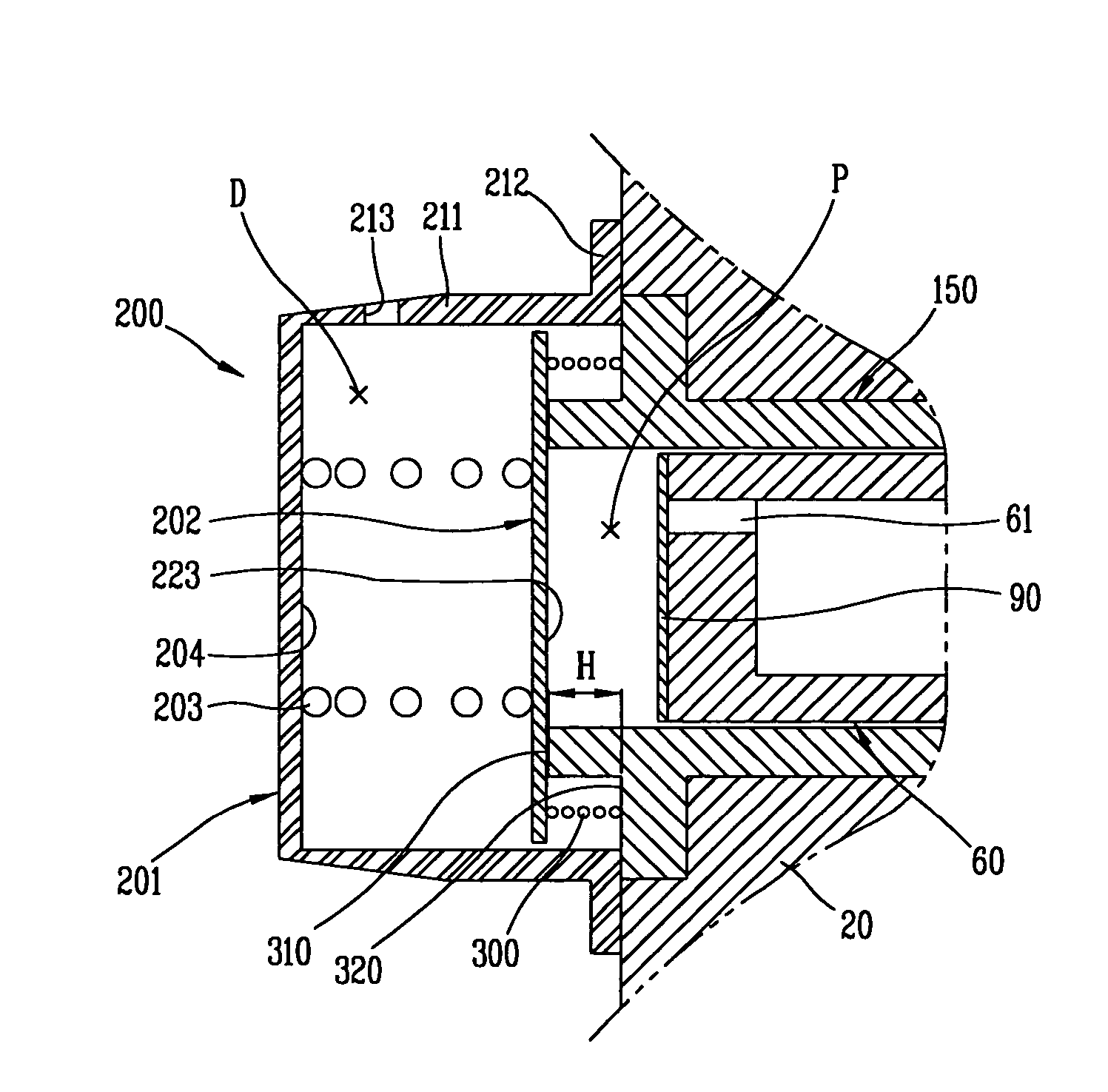
[0032]FIG. 3 is a sectional view showing a discharge valve assembly of a reciprocating compressor in accordance with the present invention.

[0033]As shown, the discharge valve assembly 200 of the reciprocating compressor in accordance with the present invention includes: a discharge valve 202 for opening or closing a compression space (P) for compressing a refrigerant in a cylinder 150; a valve spring 203 elastically supporting the discharge valve 202 as its one end is connected to the discharge valve 202; a discharge cover 201 provided with a support surface 204 connected to the valve spring 203, for covering an end of the cylinder 150, receiving the discharge valve 202 and the valve spring 230 and forming a discharge space (D) of a refrigerant; and a buffer member 300 attached to an outer mounting surface 320 of the cylinder 150, for lessening an impact by coming in contact with the discharge valve 202 in advance before the discharge valve 202 contacts with the cylinder 150 to clos...

second embodiment

[0052]FIG. 4 is a sectional view showing a discharge valve assembly of the reciprocating compressor in accordance with the present invention.

[0053]In case of the second embodiment, a discharge valve 202 is formed to be stepped, and, to this end, a contact member 250 is attached to the discharge valve 202 of the first embodiment, facing the piston 60. Preferably, an outer diameter of the contact member 250 is the same as that of the contact surface 310.

[0054]In the embodiment, the compression plane 223 is formed on the contact member 250, and the buffer member 300 contacts with the discharge valve 202, except its portion where the contact member 250 is placed. The contact member 250 is adjusted in thickness to control a distance between the buffer member 300 and the discharge valve 202, and is formed on the discharge valve 202.

[0055]As so far described, the discharge valve assembly of the reciprocating motor in accordance with the present invention is provided with a buffer member 30...


PUM


Abstract

A discharge valve assembly of a reciprocating compressor comprises: a discharge valve for opening or closing a compression space for compressing a refrigerant in a cylinder; a valve spring for elastically supporting the discharge valve as its one end is connected to the discharge valve; a discharge cover provided with a support surface connected to the valve spring, and covering an end of the cylinder, receiving the discharge valve and the valve spring and simultaneously forming a discharge space of a refrigerant; and a buffer member attached to an outer mounting surface of the cylinder, for lessening an impact by contacting with the discharge valve before the discharge valve comes in contact with the cylinder to close the compression space of the cylinder. The buffer member absorbs the amount of an impact before the discharge valve contacts with the cylinder, thereby minimizing noise generation.

Description

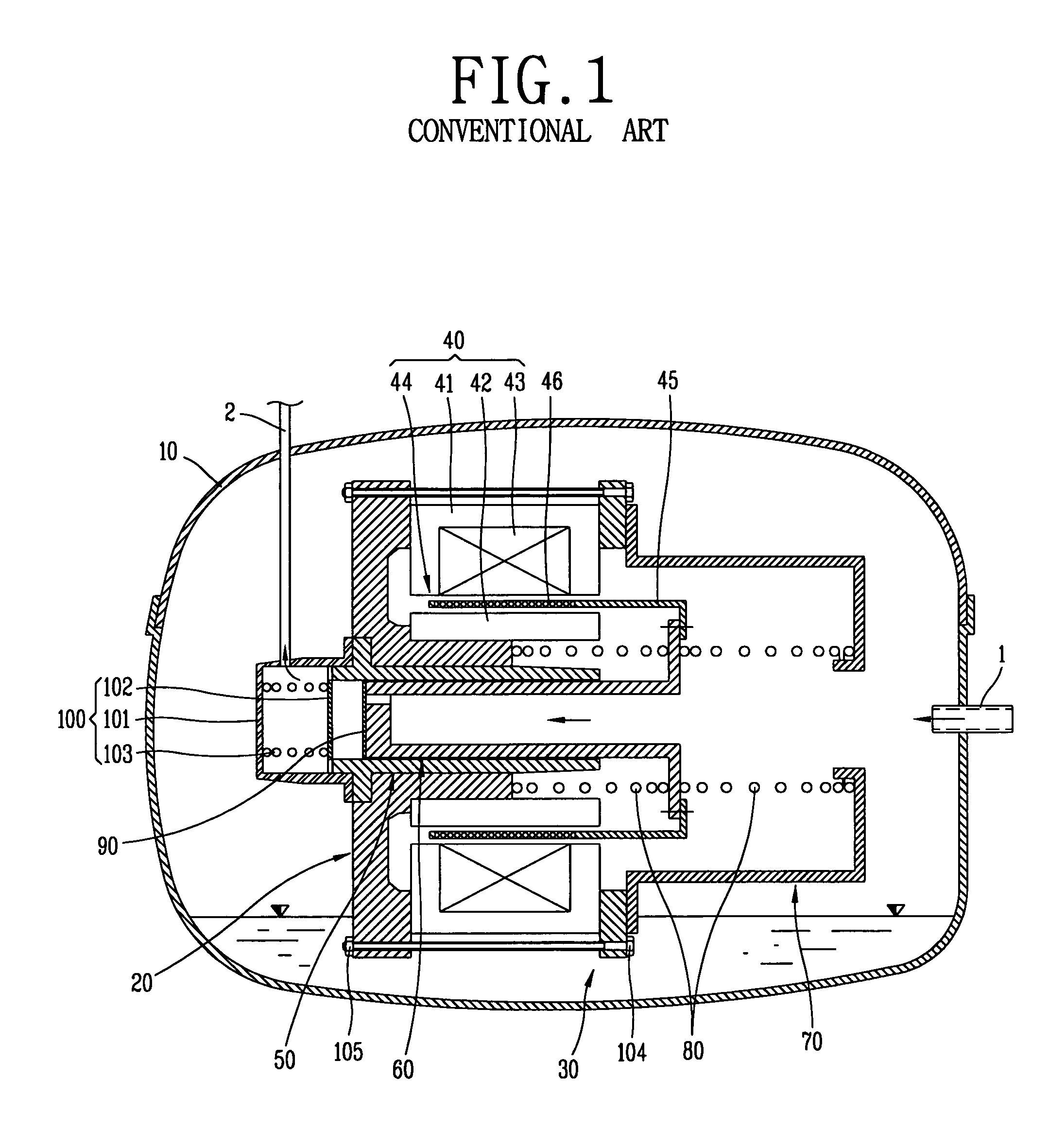
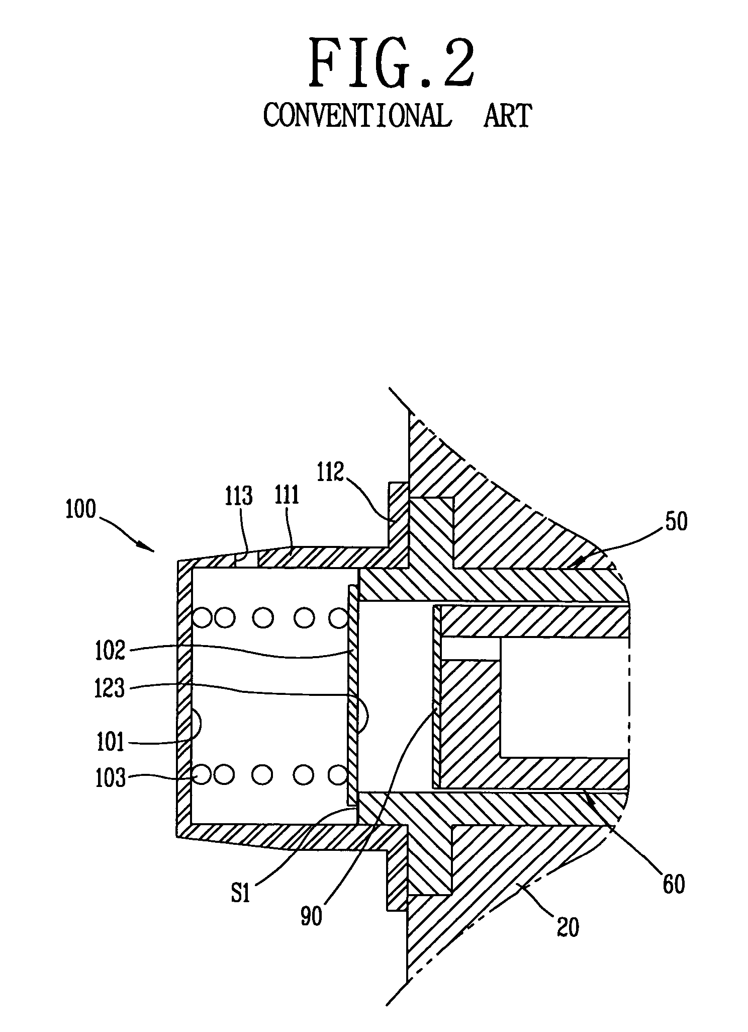
BACKGROUND OF THE INVENTION[0001]1. Field of the Invention[0002]The present invention relates to a discharge valve assembly of a reciprocating compressor, and particularly, to a discharge valve assembly of a reciprocating compressor capable of minimizing noise generation and the amount of contact impact.[0003]2. Description of the Background Art[0004]In general, a reciprocating compressor is an apparatus that sucks and compresses a refrigerant gas as a piston linearly reciprocates in a cylinder. Such a reciprocating compressor is divided into two types according to the driving mechanism. Of the two types, one is that a rotating movement of a motor is converted into a linear reciprocation and the linear reciprocation is transferred to the piston, and the other one is that a linear reciprocation of the motor is directly transferred to the piston.[0005]FIGS. 1 shows one example of a reciprocating compressor which is operated in such a manner that a linear reciprocation of a motor is di...

Claims


Application Information

Patent Timeline
Patent Type & Authority Patents(United States)
IPC IPC(8): F04B53/10
CPCF04B35/045F04B39/0055F04B39/10F04B39/08F16K15/025F16F1/04F16F3/04F16F2230/22F16F2238/026F16F2234/00Y10S251/00
Inventor KIM, YOUNG-DO
Owner LG ELECTRONICS INC
Learn More