
Heat treatment method of waste cathode materials and lithium recovery method using same

a waste cathode material and treatment method technology, applied in the direction of positive electrodes, waste accumulator reclaiming, calculation, etc., can solve the problems of reduced recovery rate, increased operation time required for cooling and restarting the heat treatment furnace, and restricted adhesion prevention of deposits on the wall surfa

Pending Publication Date: 2022-10-27
DOOSAN HEAVY IND & CONSTR CO LTD
View PDF0 Cites 0 Cited by
  • Summary
  • Abstract
  • Description
  • Claims
  • Application Information

AI Technical Summary

Benefits of technology

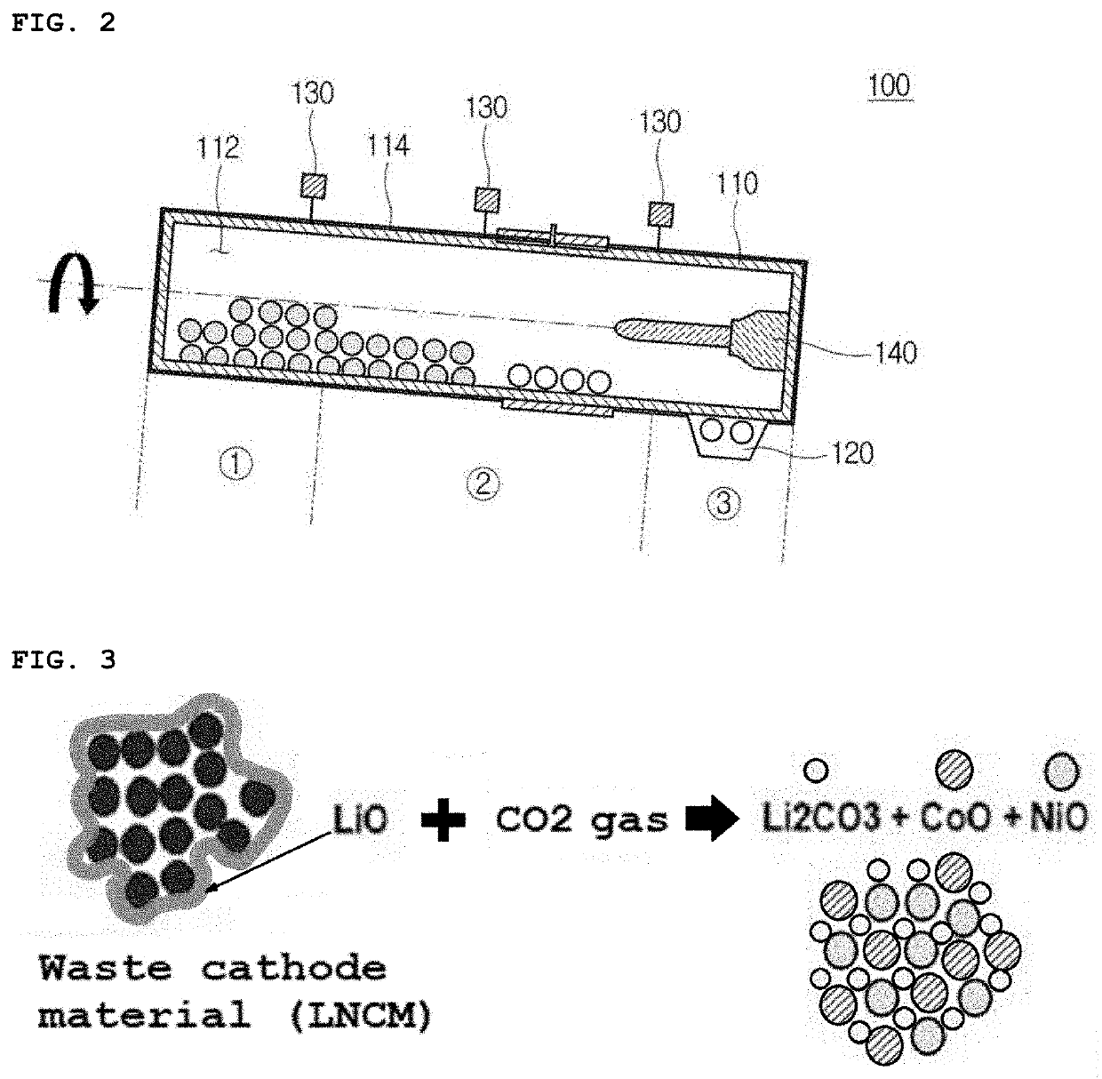
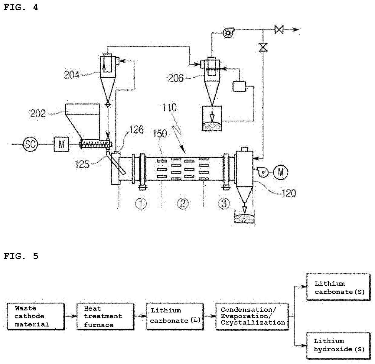
The patent describes a method for heat treatment of waste cathode material, which helps improve production efficiency by minimizing wall adhesion and CO2 gas emissions. The waste cathode material is directly heated by a hydrocarbon fluid and the heat treatment furnace rotation prevents adhesion to the wall. The resulting exhaust gas, containing CO2 gas, reacts with the waste cathode material to create a smoother reaction without the need for additional CO2 gas input. This method allows for uniform contact and reaction between the waste cathode material and exhaust gas.

Problems solved by technology

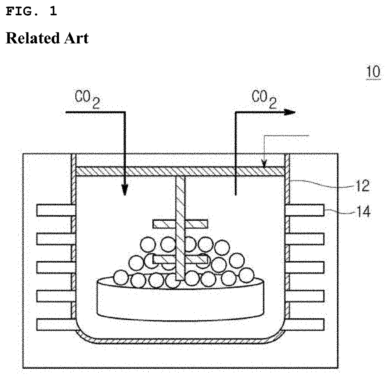
This causes many problems such as a decrease in recovery rate, an increase in operation time required for cooling and restart of the heat treatment furnace 12 to remove the produced deposits, a greater amount of deposits on the wall surface at higher temperature, a higher adhesion rate of deposits on the wall surface at higher temperature of the wall surface of the heat treatment furnace 12 than the internal set temperature that is characteristic of the indirect heating method, restricted adhesion prevention of deposits on the wall surface due to shape deformation of a stirrer, and restricted capacity increase due to increase in thickness of stirrer due to expansion of the heat treatment furnace 12.
In addition, because CO2 gas is injected from the outside to increase the amount of CO2 gas used, there are problems in that manufacturing cost increases and an environmental issue such as carbon emission occurs due to emission of unreacted CO2 gas.

Method used


Image

  • Heat treatment method of waste cathode materials and lithium recovery method using same
  • Heat treatment method of waste cathode materials and lithium recovery method using same
  • Heat treatment method of waste cathode materials and lithium recovery method using same

Examples


experimental example 1

[0093]FIG. Bis a graph showing an effect of exhaust gas recirculation in the heat treatment furnace. Referring to FIG. 8, when only the exhaust gas of the burner is used without recirculation of exhaust gas, the conductivity of lithium recovery was 11700 μs / cm, while when the exhaust gas was supplied at the exhaust gas recirculation rate of 0.5 to 0.8, the conductivity of lithium recovery was increased to 15150 μs / cm.

[0094][Experimental Example 2] Analysis for Exhaust Gas of Heat Treatment Furnace

[0095]As a result of analyzing the exhaust gas from the heat treatment furnace through a CO, CO2 and 02 measuring instrument, it was found to be CO (5 to 600 ppm), CO2 (6.0 to 12%), and 02 (7 to 10%).

[0096]In addition, it was confirmed that the lithium recovery rate decreased as the amount of 02 discharged from the inside of the heat treatment furnace increased.

[Experimental Example 3] Internal Temperature of Heat Treatment Furnace for Each Section at 800° C.

[0097]It was confirmed that the ...


PUM

PropertyMeasurementUnit
temperatureaaaaaaaaaa
internal pressureaaaaaaaaaa
inclined angleaaaaaaaaaa

Abstract

A method of heat-treating a waste cathode material to recover lithium carbonate from the waste cathode material, and a lithium carbonate recovery method using the waste cathode material heat treatment method are provided. The method of heat-treating the waste cathode material includes heating an interior of a heat treatment furnace by burning a hydrocarbon fluid in the heat treatment furnace and producing lithium carbonate (Li2CO3) and residual metal oxide by reacting a waste cathode material in the heat treatment furnace with CO2 generated during burning of the hydrocarbon fluid.

Description

CROSS REFERENCE TO RELATED APPLICATIONS[0001]This application claims priority to Korean Patent Applications Nos. 10-2021-0053108, filed on Apr. 23, 2021 and 10-2021-0079638, filed on Jun. 18, 2021, the disclosures of which are incorporated herein by reference in their entireties.BACKGROUND1. Field[0002]Apparatuses and methods consistent with exemplary embodiments relate to a waste cathode material heat treatment method for recovering lithium from the waste cathode material, and a lithium recovery method using the same.2. Description of the Related Art[0003]In the process of manufacturing a cathode material for a secondary battery, a large amount of waste cathode material that is discarded as defective or scraps is generated, and an attempt has been made to recover a transition metal including lithium from the waste cathode material.[0004]According to a method of recovering lithium carbonate or lithium hydroxide through heat treatment from waste cathode materials such as NCM (i.e., n...

Claims


Application Information

Patent Timeline
Patent Type & Authority Applications(United States)
IPC IPC(8): C01D15/08H01M10/54C01D15/02
CPCC01D15/08H01M10/54C01D15/02H01M2004/028B01J6/002B01J6/004B01J8/10B01J2208/00504H01M10/052
Inventor YOU, JANG YONGKANG, WEE KWANJO, HO YONGLEE, CHAE SOO
Owner DOOSAN HEAVY IND & CONSTR CO LTD
Learn More