
Image forming apparatus and image forming method

a technology of image forming and forming apparatus, which is applied in the direction of electrographic process apparatus, instruments, optics, etc., can solve the problems of inability to meet the requirements of image forming, so as to reduce the sub-scan length of the image pattern detected, the effect of minimizing the consumed toner amount and the required time for forming

Active Publication Date: 2015-11-17
RICOH KK
View PDF15 Cites 1 Cited by
  • Summary
  • Abstract
  • Description
  • Claims
  • Application Information

AI Technical Summary

Benefits of technology

The patent describes a device that can make images faster and use less toner by detecting the rotary motion of a part and reducing the amount of movement needed to create a pattern. This technology reduces the amount of toner used and the time required to create an image.

Problems solved by technology

Therefore, when a development gap, which is a distance between the developer carrier and the image carrier, fluctuates due to the rotary oscillation of the image carrier, the electric field also fluctuates and causes image density changes or fluctuations.
With regard to the uneven sensitivity of the image carrier, if the image carrier is manufactured using a high-precision production method in order to decrease the number of sensitivity errors, manufacturing costs soar.
Density fluctuation caused by the uneven sensitivity of the image carrier also has other causes.
However, the above technique has a disadvantage in that, if the developing bias alone is controlled, even though the solid density correction is performed satisfactorily, the halftone density correction cannot be performed well.
As a result, such disadvantages will occur that the toner consumption amount increases, the load on the cleaning device increases, down time is lengthened, and the like.
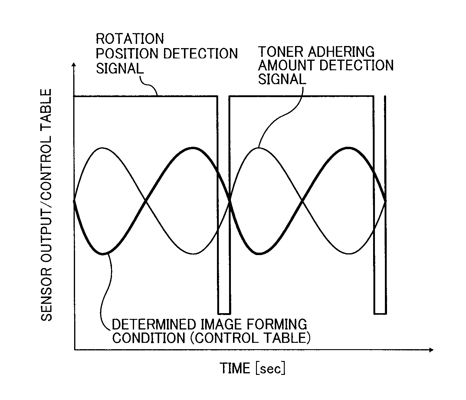
In this case, there is a case in which the detection signal of the rotational position detection sensor does not come at a head of the image pattern due to the rotation start position of the image carrier to form the image pattern, so that the data acquisition becomes inadequate.
For example, substantially one cycle data of the image carrier becomes useless and toner used for the image pattern not used for the average acquisition becomes a waste, leading to a toner yield problem.

Method used


Image

  • Image forming apparatus and image forming method
  • Image forming apparatus and image forming method
  • Image forming apparatus and image forming method

Examples


Embodiment Construction

[0045]Hereinafter, embodiments of the present invention will now be described with reference to the drawings.

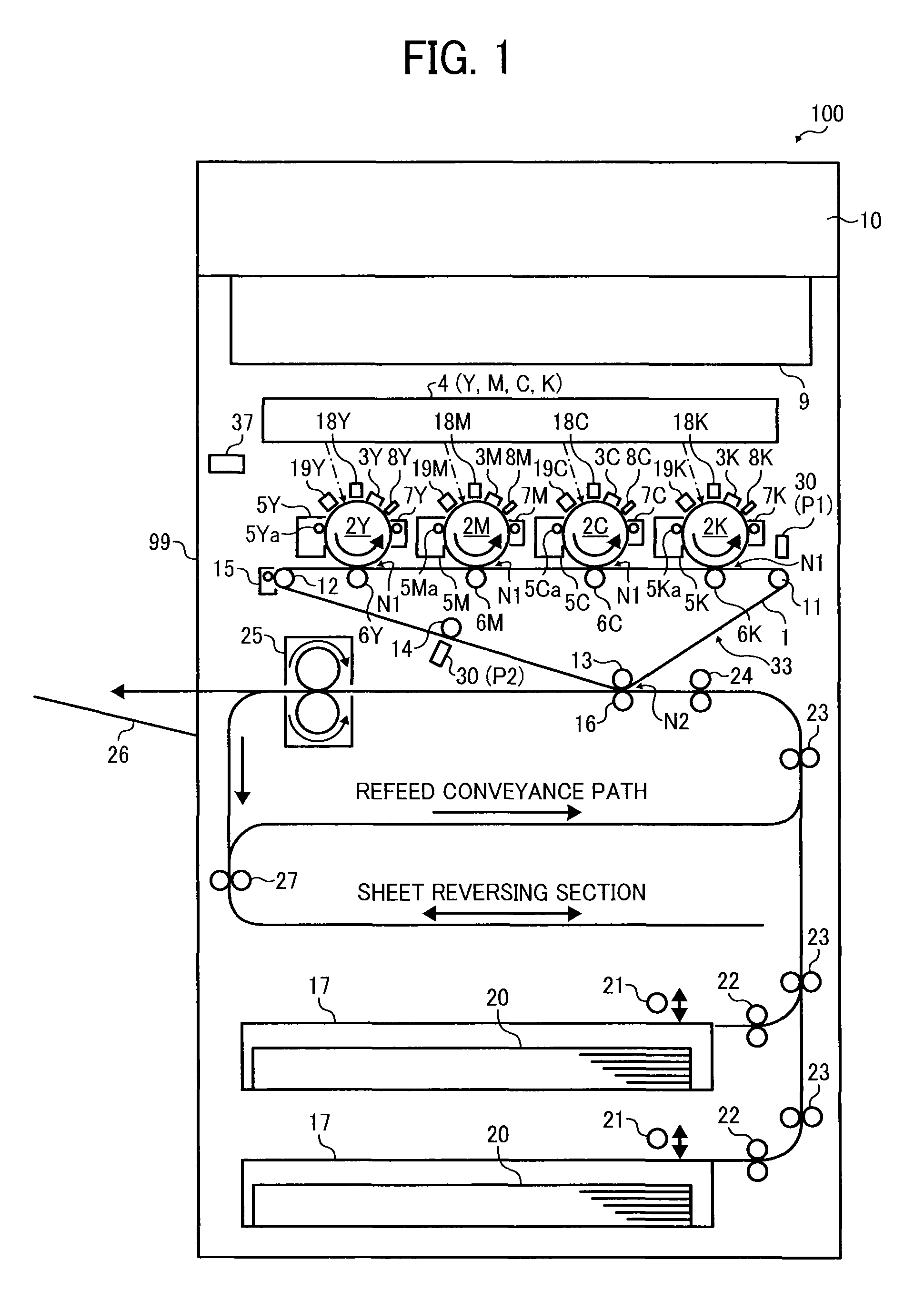
[0046]FIG. 1 shows a schematic view of an image forming apparatus to which the present invention may be applied. As illustrated in FIG. 1, a full color copier, which employs a 4-storied tandem-type intermediate transfer method, is shown as an example of the application of the present invention; however, the present invention may be applied to other types of image forming apparatuses, including a 4-storied tandem-type direct transfer method applied full color copier or one-drum type intermediated transfer method applied full color copier, and the like. Further, the present invention may be applied to the one-drum type direct transfer method applied monochrome apparatus.

[0047]As illustrated in FIG. 1, the image forming apparatus 100 includes: an intermediate transfer belt 1 being an intermediate transfer body as an image carrier; and photoreceptor drums 2Y, 2M, 2C, and 2K as ro...


PUM


Abstract

An image forming apparatus includes an image carrier; a developer carrier configured to adhere toner onto the image carrier; an image density detector to detect a density of an image on the image carrier formed by the developer carrier adhering the toner on the image carrier; a rotary member to form an image pattern of which density is detected by the image density detector; and a rotational position detector to detect a rotational position of the rotary member. In the image forming apparatus, the image pattern is generated based on the rotational position detected by the rotational position detector and the rotary member that the rotational position detector detects the rotational position thereof is either the image carrier or the developer carrier.

Description

CROSS-REFERENCE TO RELATED APPLICATION[0001]The present application claims priority pursuant to 35 U.S.C. §119 from Japanese patent application number 2012-057846, filed on Mar. 14, 2012, the entire disclosure of which is incorporated by reference herein.BACKGROUND[0002]1. Technical Field[0003]The present invention relates to an image forming apparatus forming an image using toner, such as a copier, a printer, a facsimile machine, a plotter, or a multi-function apparatus having at least one capability of the above devices. The present invention also relates to an image forming method employed in such an image forming apparatus and capable of detecting density of the image formed thereby.[0004]2. Related Art[0005]An image forming apparatus that employs a so-called electrophotographic method to form an image with toner has been known, as disclosed by, for example, JP-H09-62042-A, JP-3825184-B, and JP-2000-98675-A. Such an image forming apparatus forms an image in such a manner that a ...

Claims


Application Information

Patent Timeline
Patent Type & Authority Patents(United States)
IPC IPC(8): G03G15/01G03G15/00G03G15/08G03G13/22G03G15/22
CPCG03G15/5058G03G15/0849G03G15/5008G03G13/22G03G15/22G03G2215/00037G03G2215/00063G03G2215/0161G03G2215/0129G03G2215/0141G03G2215/0164
Inventor KANEKO, SATOSHIKATO, SHINJIISHIBASHI, HITOSHIHIRAI, SHUJIYAMANE, JUNKUDO, KOICHISUZUKI, SHINGO
Owner RICOH KK
Learn More