Flat circuit connector with pivoted actuator

a technology of actuators and flat circuits, applied in the direction of coupling contact members, coupling device connections, coupling/disassembly parts, etc., can solve the problems of deformation or damage of contact points on flat circuits, loose or free insertion force connectors,

Inactive Publication Date: 2009-06-30
MOLEX INC
View PDF24 Cites 15 Cited by
  • Summary
  • Abstract
  • Description
  • Claims
  • Application Information

AI Technical Summary

Benefits of technology

[0007]An object, therefore, of the invention is to provide a new and improved flat circuit connector of the character described.

Problems solved by technology

In fact, some of the contacts on the flat circuit often were deformed or damaged.
Unfortunately, such zero insertion force connectors often are too loose or free during insertion of the flat circuit.

Method used


Image

  • Flat circuit connector with pivoted actuator
  • Flat circuit connector with pivoted actuator
  • Flat circuit connector with pivoted actuator

Examples


first embodiment

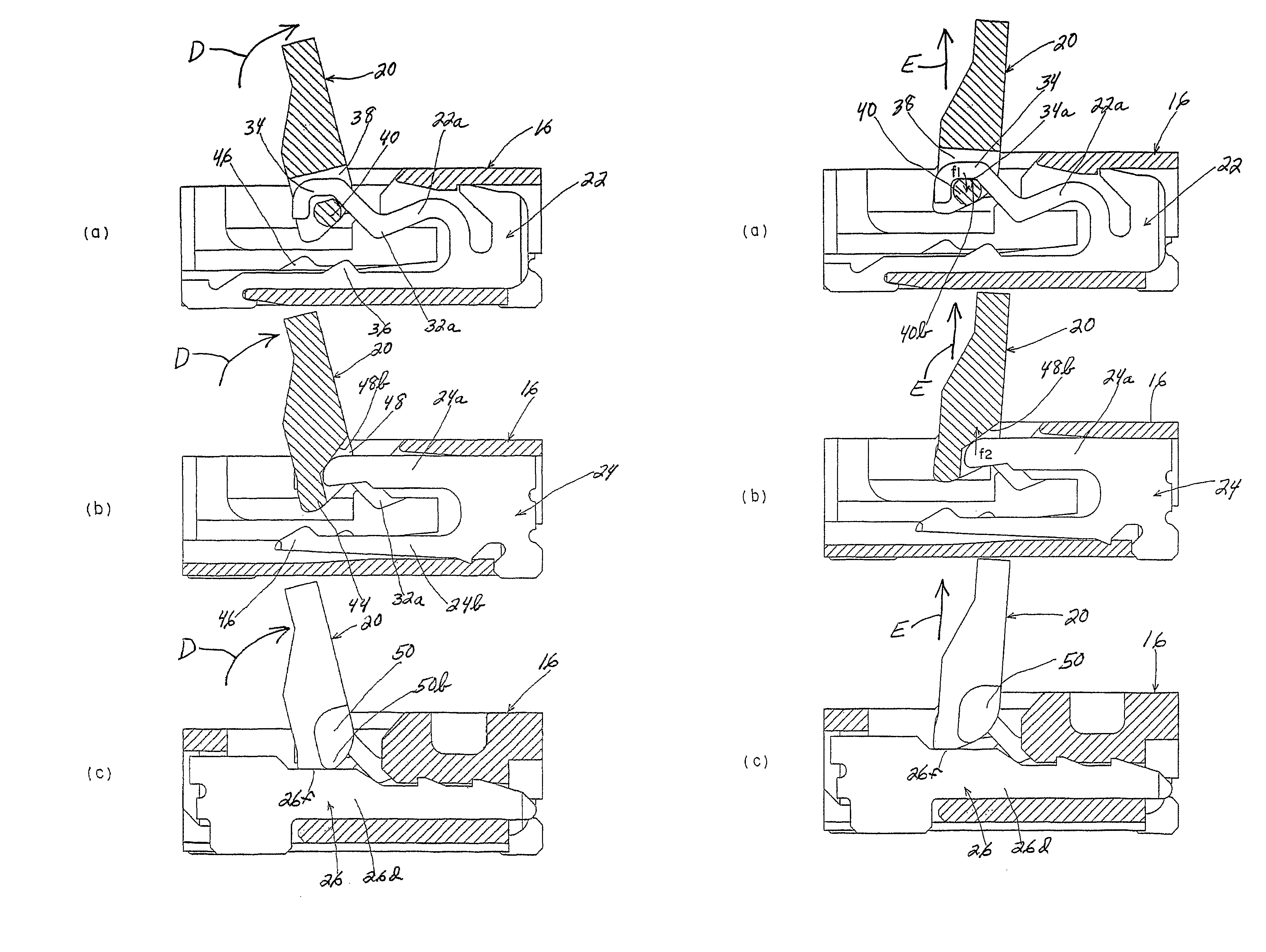
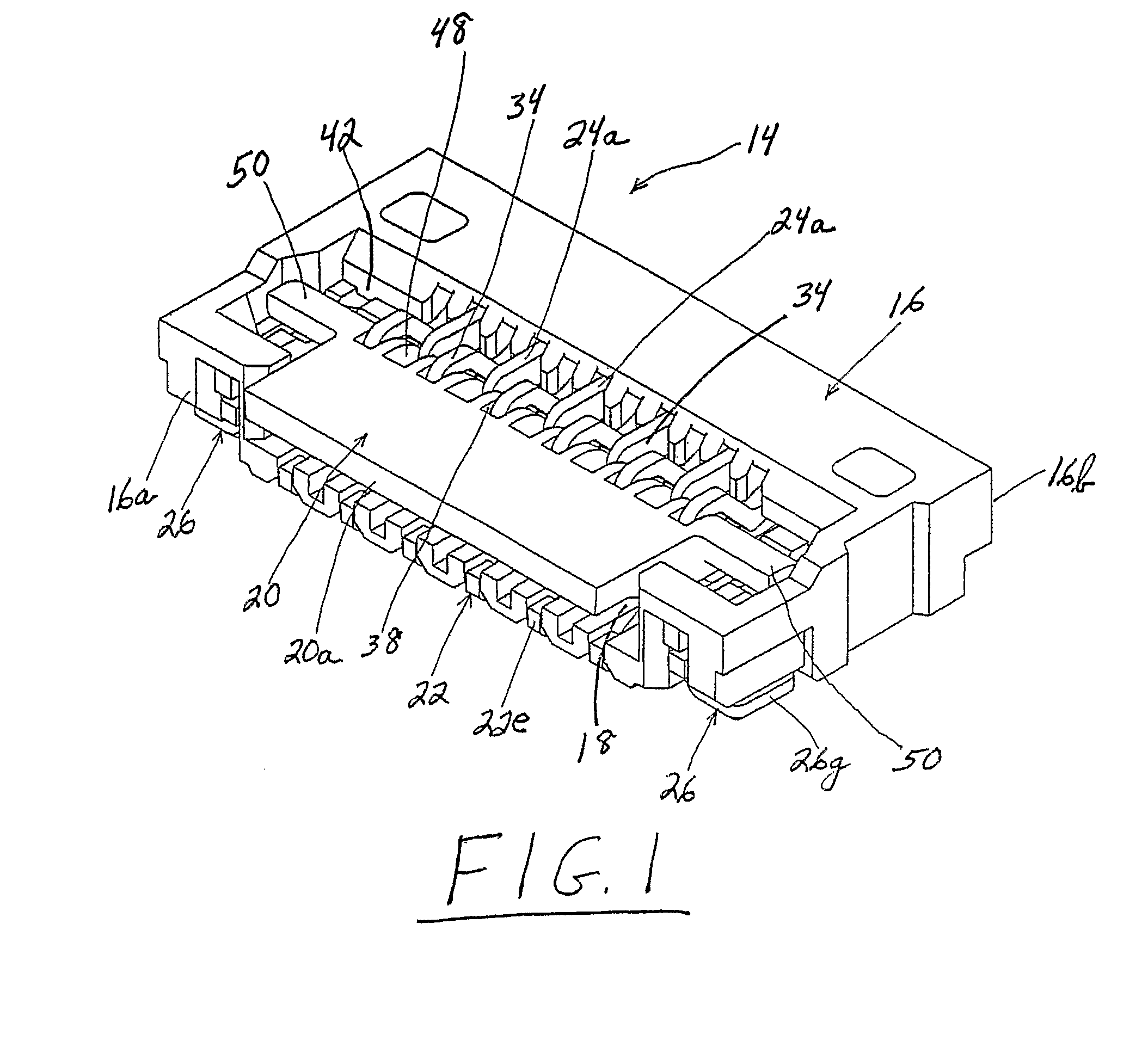
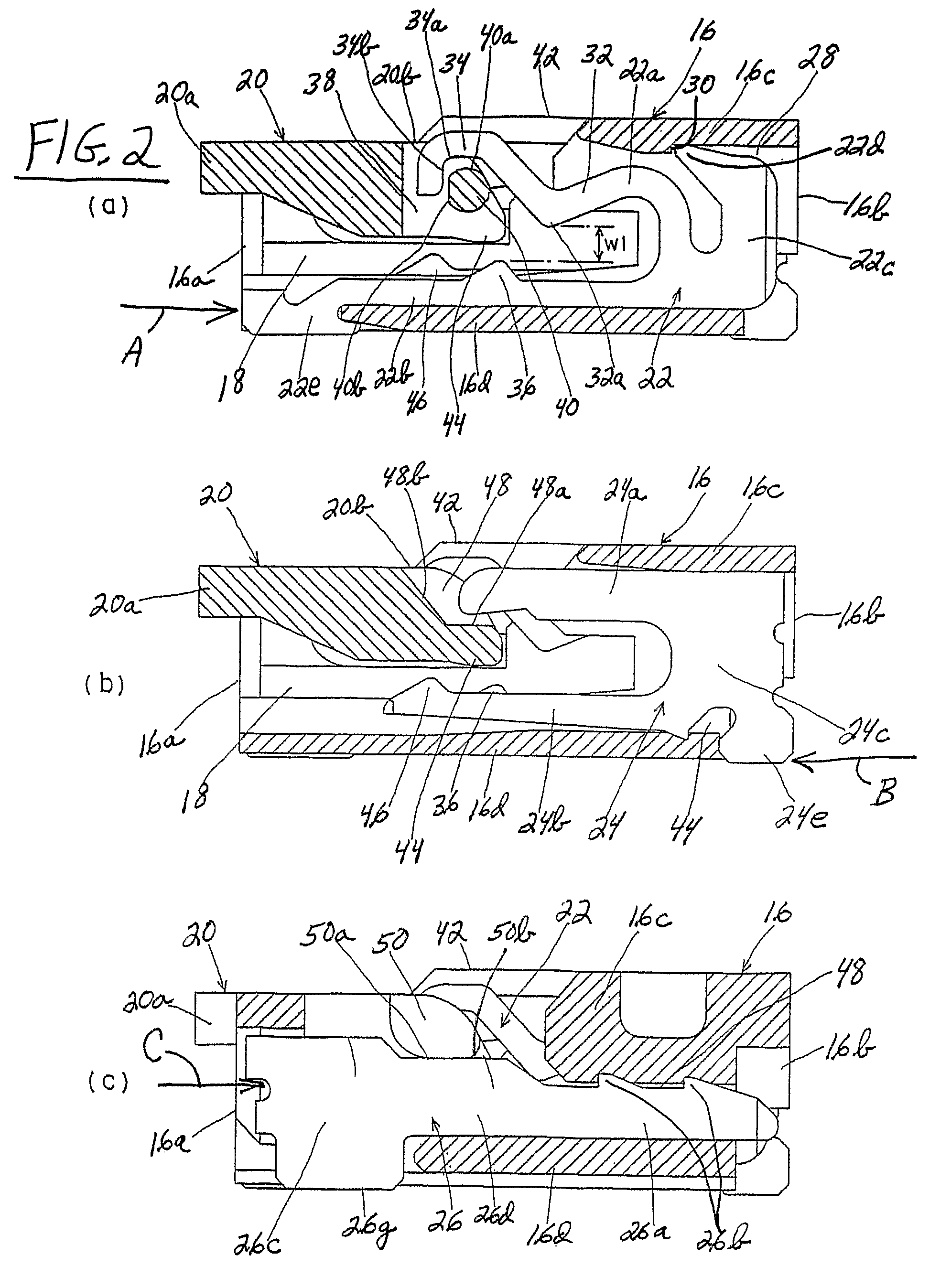
[0028]Referring to the drawings in greater detail, and first to FIGS. 1 and 2, the invention is embodied in a flat circuit electrical connector, generally designated 14 (FIG. 1) according to the invention. The connector is designed for mounting on a printed circuit board (not shown). The connector includes a dielectric housing, generally designated 16, having a front end 16a and a rear end 16b. The housing defines an opening 18 which opens at the front end for receiving an end of a flat circuit as will be seen hereinafter. The housing is a one-piece structure molded of dielectric material such as plastic or the like. An actuator, generally designated 20, is movably mounted for pivotal movement between an open position (described hereinafter) allowing the flat circuit to be inserted into opening 18 with substantially zero insertion forces and a closed position shown in FIGS. 1 and 2 biasing the flat circuit against contact portions of a plurality of terminals, again as will be descri...

second embodiment

[0045]FIGS. 11 and 12 show a flat circuit connector, generally designated 14A. In this embodiment, upper hook arms 22a of first terminals 22 do not have downwardly projecting bearing portions 32a. In addition, dielectric housing 16 has a recess 66 to accommodate the leading end of a flat circuit. Otherwise, like reference numerals have been applied in FIGS. 11 and 12 corresponding to like components described above in relation to FIGS. 1-8.


PUM


Abstract

An electrical connector is provided for terminating a flat electrical circuit. The connector includes a dielectric housing having an opening at a front end thereof for receiving an end of the flat circuit. A plurality of terminals are mounted on the housing in a side-by-side array and spaced laterally along the opening. An actuator is movably mounted for pivotal movement between an open position allowing the flat circuit to be inserted into the opening with substantially zero insertion forces, a closed position biasing the flat circuit against contact portions of the terminals and an intermediate position whereat the flat circuit is tentatively held in stable condition while allowing readjustment thereof.

Description

FIELD OF THE INVENTION[0001]This invention generally relates to the art of electrical connectors and, particularly, to a connector for terminating a flat circuit, such as a flat flexible circuit, a flexible printed circuit or other flat electrical cable.BACKGROUND OF THE INVENTION[0002]A wide variety of electrical connectors have been designed for terminating flat cables or circuits, such as flat flexible cables, flexible printed circuits or the like. A typical connector for flat circuits includes a dielectric housing molded of plastic material, for instance. The housing has an elongated opening or slot for receiving an end of the flat circuit which has generally parallel, laterally spaced conductors exposed across the end. A plurality of terminals are mounted in the housing and are spaced laterally along the slot, with contact portions of the terminals engageable with the laterally spaced conductors of the flat circuit. An actuator often is movably mounted on the housing for moveme...

Claims


Application Information

Patent Timeline
Patent Type & Authority Patents(United States)
IPC IPC(8): H01R12/24H01R12/79
CPCH01R12/79H01R12/82
Inventor TAKETOMI, KOUSUKEHORINO, ATSUHITOKANEKO, TOMONARI
Owner MOLEX INC
Why Eureka
Try Eureka