Circuits, devices and methods for regulator minimum load control

a regulator and minimum load technology, applied in the direction of electric variable regulation, process and machine control, instruments, etc., can solve the problems of undesirable heat and waste of current, waste of dummy load 136,

Active Publication Date: 2009-06-30
TEXAS INSTR INC
View PDF5 Cites 12 Cited by
  • Summary
  • Abstract
  • Description
  • Claims
  • Application Information

AI Technical Summary

Problems solved by technology

However, maintaining minimum loading through use of dummy load 136 is wasteful.
Both the heat and the wasted current are undesirable.

Method used


Image

  • Circuits, devices and methods for regulator minimum load control
  • Circuits, devices and methods for regulator minimum load control
  • Circuits, devices and methods for regulator minimum load control

Examples


Embodiment Construction

[0021]The present invention is related to voltage regulators. More particularly, the present invention is related to circuits, systems and methods for maintaining voltage regulators at a desired loading condition.

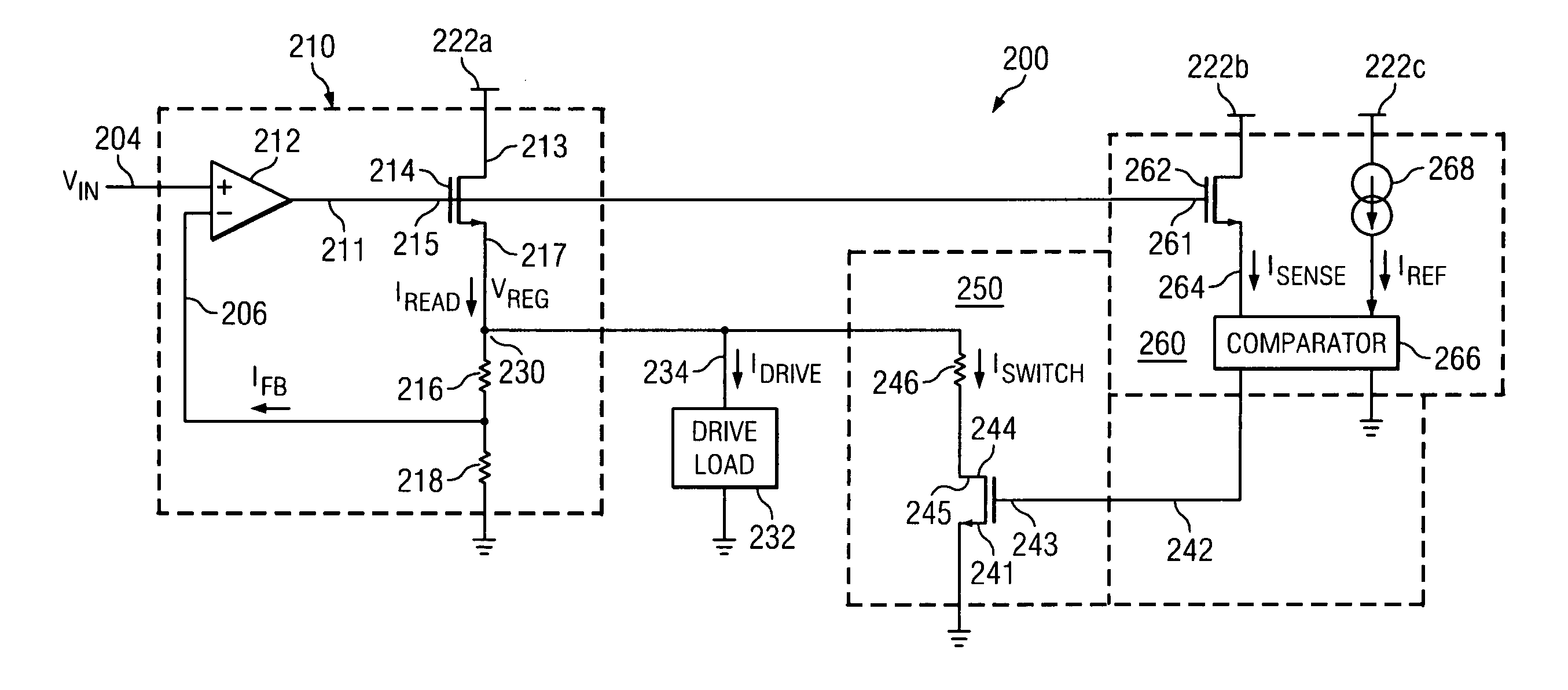
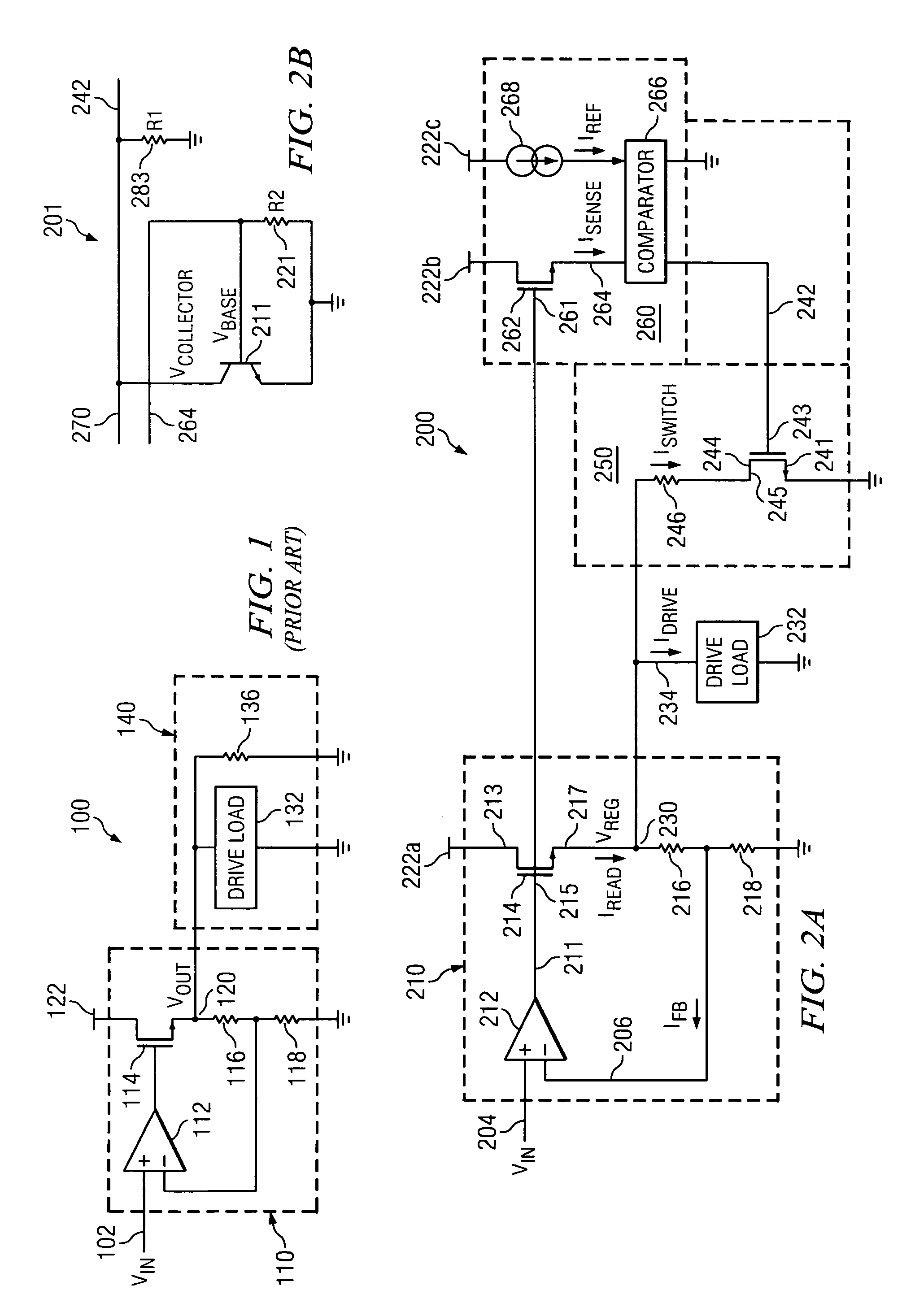
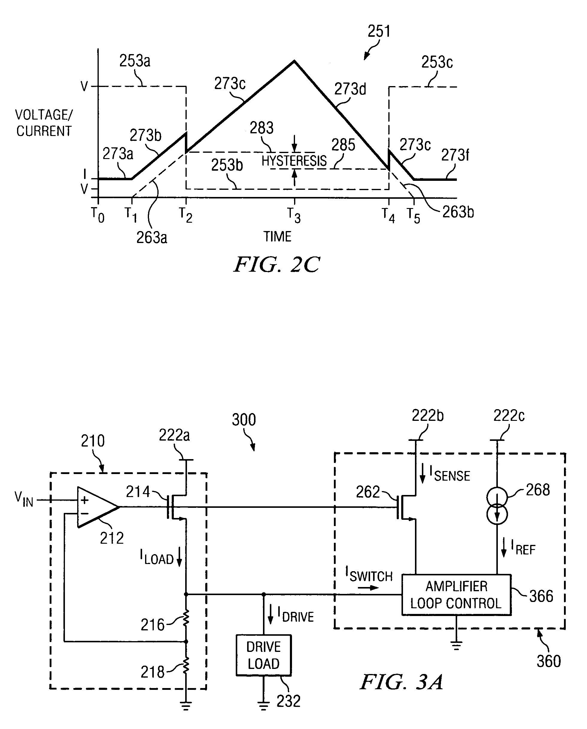
[0022]Various embodiments of the present invention provide circuits, systems and methods for regulator load control. Such embodiments may include a load control circuit and a switched load. The load control circuit may include a reference current and a sense current representative of a load current. In addition, the load control circuit may include a comparator circuit that drives a load control signal in response to a comparison between the reference current and the sense current. The load control signal is operable to switch the switched load between various supported load factors. As used herein, the term “load factor” is used in its broadest sense to mean any circuit load. In some cases, the load is a purely resistive load. In other cases, the load is a purely capacitiv...


PUM


Abstract

Systems, methods and circuits for regulator minimum load control. In one particular case, a system is provided that includes a load control circuit and a switched load. The load control circuit includes a reference current, and a sense current representative of a load current. In addition, the load control circuit includes a comparator circuit that drives a control signal in response to a comparison between the reference current and the sense current. The switched load is electrically coupled to a load voltage signal to provide loading to the load voltage signal. The switched load is operable to switch between a first loading factor and a second loading factor in response to the control signal.

Description

BACKGROUND OF THE INVENTION[0001]The present invention is related to voltage regulators. More particularly, the present invention is related to circuits, systems and methods for maintaining voltage regulators at a desired loading condition.[0002]A prior art regulated system 100 is depicted in FIG. 1. Regulated system 100 includes a voltage regulator 110 that regulates an input voltage 102, and outputs a regulated voltage 120 to an overall load 140. Voltage regulator 110 includes an operational amplifier 112 receiving input voltage 102 and driving a FET 114. The drain of FET 114 is tied to a voltage source 122, and the source of FET 114 drives regulated voltage 120. A feedback loop of operational amplifier 112 is driven by the regulated voltage signal as divided by resistors 116, 118.[0003]Overall load 140 includes a drive load 132 and a dummy load 136. Dummy load 136 is a resistive load, and is included to assure that voltage regulator 110 is always supplying at least some load. By ...

Claims


Application Information

Patent Timeline
Patent Type & Authority Patents(United States)
IPC IPC(8): G05F1/40
CPCG05F1/618
Inventor CARPENTER, JR., JOHN H.THOMPSEN, BRETT J.AMEY, BENJAMIN L.YOU, ZHIHONGDEVORE, JOSEPH A.
Owner TEXAS INSTR INC
Why Eureka
Try Eureka