
Widgets displayed and operable on a surface of a volumetric display enclosure

a volumetric display and widget technology, applied in the direction of mechanical pattern conversion, optical elements, instruments, etc., can solve the problems of intermingling widgets and data, inability to meet the needs of people, and scant attention given to the interface or the way in which people interface with these types of displays

Inactive Publication Date: 2009-06-30
AUTODESK INC
View PDF47 Cites 19 Cited by
  • Summary
  • Abstract
  • Description
  • Claims
  • Application Information

AI Technical Summary

Benefits of technology

[0009]It is an aspect of the present invention to provide a system that allows 2D widgets or graphical user interfaces to be used in a 3D volumetric display.
[0010]It is another aspect of the present invention to position widgets within a volumetric display at positions where they are useful for direct and simple interaction.
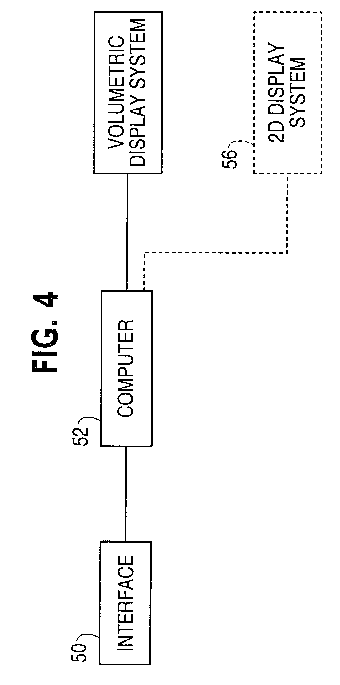
[0014]The above aspects can be attained by a system that places user interface widgets in positions in a 3D volumetric display where they can be used with ease and directness. The widgets are placed on the shell or outer edge of a volumetric display, in a ring around the outside bottom of the display, in a plane within the display and / or at the users focus of attention. Virtual 2D widgets are mapped to volumetric display voxels and control actions in the 3D volume are mapped to controls of the widgets.

Problems solved by technology

As a result, the man-machine interface to or the ways in which people interface with these types of displays is receiving scant attention.
This is a particular problem when the widget is a two-dimensional (2D) interface, such as menu, a file tree, a virtual keyboard, or a display / view of a two dimensional document, such as a list or spreadsheet.
This can result in the intermingling of widgets and data, which may not be desirable.
Additionally, complex 3D selection techniques may be needed if the 2D widget is placed in the 3D scene space to avoid selecting scene elements when the widget is intended.

Method used


Image

  • Widgets displayed and operable on a surface of a volumetric display enclosure
  • Widgets displayed and operable on a surface of a volumetric display enclosure
  • Widgets displayed and operable on a surface of a volumetric display enclosure

Examples


Embodiment Construction

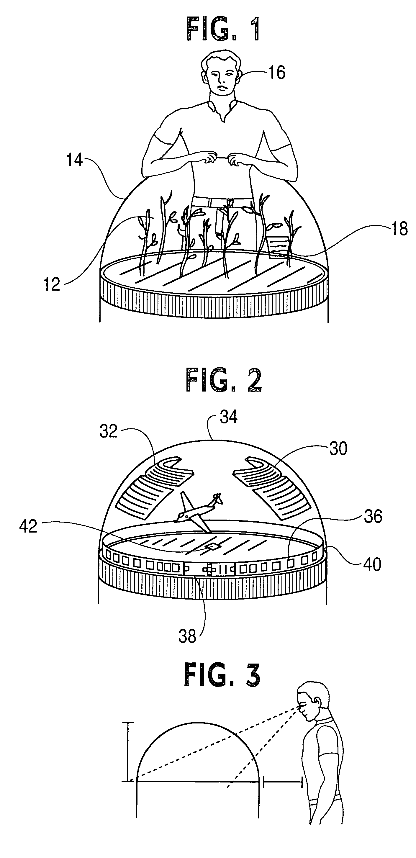
[0024]Volumetric displays allow a user to have a true three-dimensional view of a scene 12 and are typically provided in the form of a dome 14, as depicted in FIG. 1. The user 16, as can be surmised from FIG. 1, move about the dome 14 to view different parts of the scene 12. From a particular viewpoint, a planar 2D widget 18 within the volumetric display and which may have icons, controls etc. within it can be in a position such that it is difficult to access by the user.

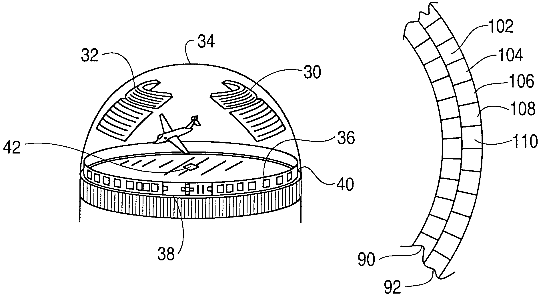
[0025]There are a number of different solutions to this problem. One solution is to place the 2D widgets 30 and 32 on the inside surface of the volumetric display enclosure 34, as depicted in FIG. 2; that is, reserve portions of the shell of the display for graphical user interfaces. Conventional pointing and manipulation techniques, such as touching a touch sensitive surface of the enclosure 34, can be used to interact with the widgets. The widgets also do not get mixed up with data or other data based graphics wit...


PUM


Abstract

The present invention is a system that places 2D user interface widgets in optimal positions in a 3D volumetric display where they can be easily used based on the knowledge user have about traditional 2D display systems. The widgets are placed on a shell or outer edge surface of a volumetric display, in a ring around the outside bottom of the display, in a vertical or horizontal plane within the display and / or responsive to the users focus of attention. Virtual 2D widgets are mapped to volumetric voxels of the 3D display system. This mapping includes any mapping between a 2D representation or virtual display map of the widget to the corresponding voxels. For example, a 2D texture map of the widget image may be mapped into voxels. Control actions in the 3D volume initiated by conventional control devices, such as a mouse or a touch sensitive dome enclosure surface, are mapped to controls of the widgets and appropriate control functions are performed.

Description

CROSS-REFERENCE TO RELATED APPLICATION(S)[0001]This application is related to and claims priority to U.S. provisional application entitled User Interfaces For Volumetric Displays, having Ser. No. 60 / 350,952, by Kurtenbach et al, filed Jan. 25, 2002, this application is also related to U.S. application entitled Three Dimensional Volumetric Display Input And Output Configurations, having Ser. No. 10 / 183,970, by Kurtenbach et al, filed concurrently herewith, to U.S. application entitled Volume Management System For Volumetric Displays, having Ser. No. 10 / 183,966, by Kurtenbach et al, filed herewith, to U.S. application entitled Graphical User Interface Widgets Viewable And Readable From Multiple Viewpoints In A Volumetric Display, having Ser. No. 10 / 183,968, by Fitzmaurice et al, filed concurrently herewith, to U.S. application entitled A System For Physical Rotation of Volumetric Display Enclosures To Facilitate Viewing, having Ser. No. 10 / 188,765, by Balakrishnan et al, filed concurr...

Claims


Application Information

Patent Timeline
Patent Type & Authority Patents(United States)
IPC IPC(8): G06T17/00G02B27/22G06F3/00G06F3/01G06F3/033G06F3/041G06F3/048
CPCG02B27/2271G06F3/011G06F3/0346G06F3/041G06F3/04812G06F3/04815G02B30/50G06T17/00
Inventor FITZMAURICE, GEORGE WILLIAMBALAKRISHNAN, RAVINKURTENBACH, GORDON PAUL
Owner AUTODESK INC
Learn More