Tubular rotary joint

a rotary joint and tube technology, applied in the direction of branching pipes, rigid supports of bearing units, mechanical equipment, etc., can solve the problems of high radial and axial forces, high pressure also arises when conducting polymer melts, and cannot be taken up by slide bearings

Inactive Publication Date: 2009-07-07
OERLIKON TEXTILE GMBH & CO KG
View PDF19 Cites 9 Cited by
  • Summary
  • Abstract
  • Description
  • Claims
  • Application Information

AI Technical Summary

Benefits of technology

[0008]A special advantage of the invention is that the connection between the holder and the connection body is formed by means of a shaft-hub connection. For this purpose, the connection body comprises a shaft journal, which is mounted in a bearing bore of the holder. The bearing bore penetrates the distribution chamber such that loads acting on one side of the connection body and resulting from the fluid pressures within the distribution chamber are avoided.
[0009]This improved version of the tubular rotary joint is particularly advantageous, in which the bearing bore completely penetrates the holder to form two bearing points so that approximately equal pressure forces act on the shaft journal in both the bearing points. The bearing bore is preferably designed in the bearing points such that its diameter is of equal size so that the pressures acting on the shaft journal are compensated.
[0010]Seals for sealing the distribution chamber are assigned advantageously to the bearing points between the holder and the shaft journal.
[0011]The seals in the bearing points can be formed using temperature-resistant packing glands. It is particularly advantageous if the packing glands are held by adjustable pre-tensioning means in order to enable a complete sealing of the distribution chamber. On the other hand, it is particularly advantageous when conducting a polymer melt if a small quantity of the polymer can be guided out of the bearing points on both sides of the distribution chamber in order to discharge, for example, any broken-down polymer material.
[0012]In conjunction with slide bearings, even gap seals are implemented preferably between the shaft journal and the holder.
[0013]The shaft journal is mounted preferably using a slide bearing support, so that it is possible to implement small shaft bearing clearances having a diameter of <0.15 mm.

Problems solved by technology

However, in addition to high temperatures, high pressures also arise when conducting polymer melts.
These high pressures lead to correspondingly high radial and axial forces.
However, such high-pressure forces cannot be taken up by the slide bearing, particularly in the design disclosed in the prior art.
However, according to the invention, roller bearings have a limited suitability for high temperatures.
Another problem of the tubular rotary joints disclosed in the prior art is that a free rotatability of the connection body in the holder is not ensured at high pressures.
In particular, forces acting only on one side of the connection body can be particularly detrimental.

Method used


Image

  • Tubular rotary joint
  • Tubular rotary joint
  • Tubular rotary joint

Examples


Embodiment Construction

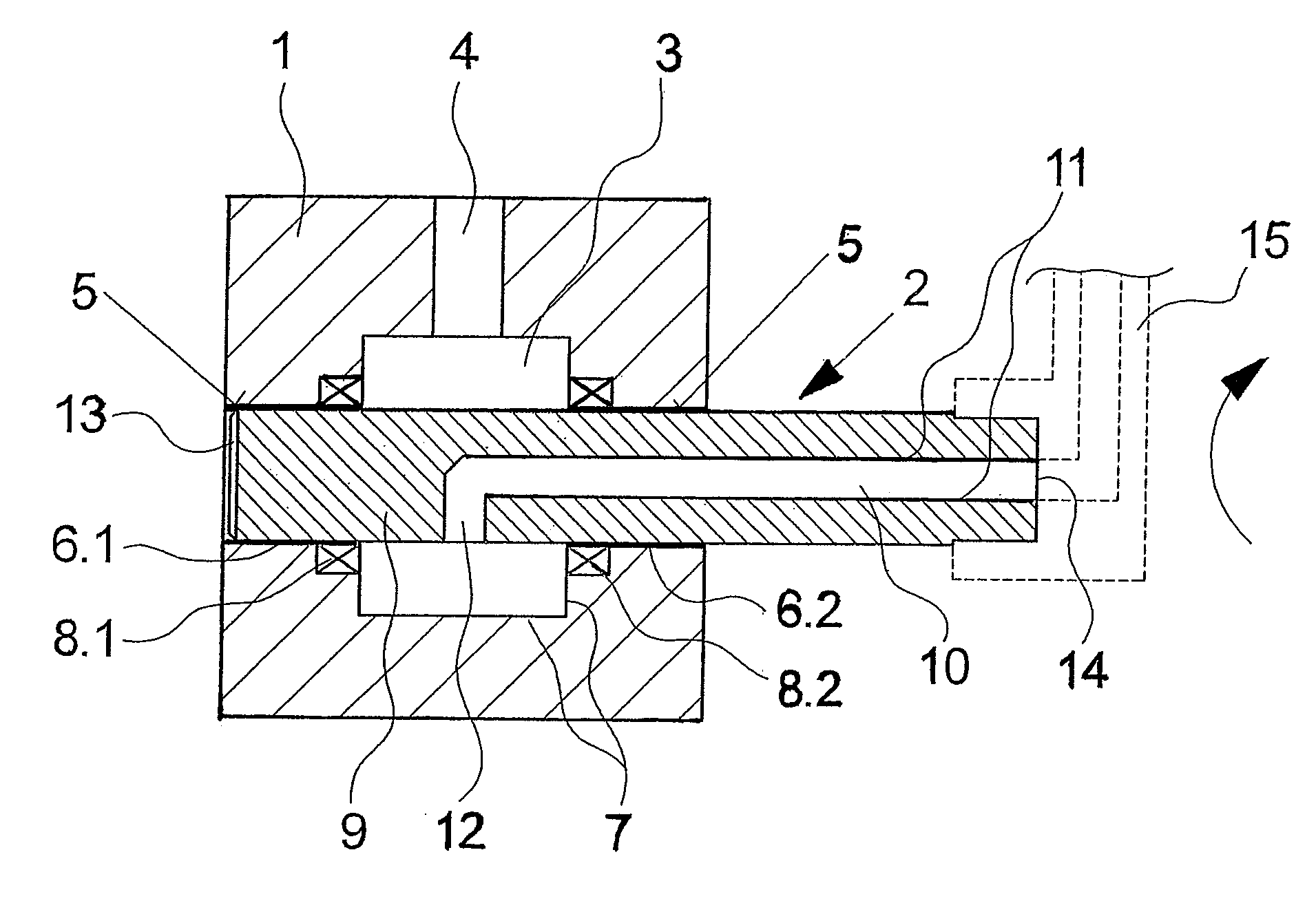
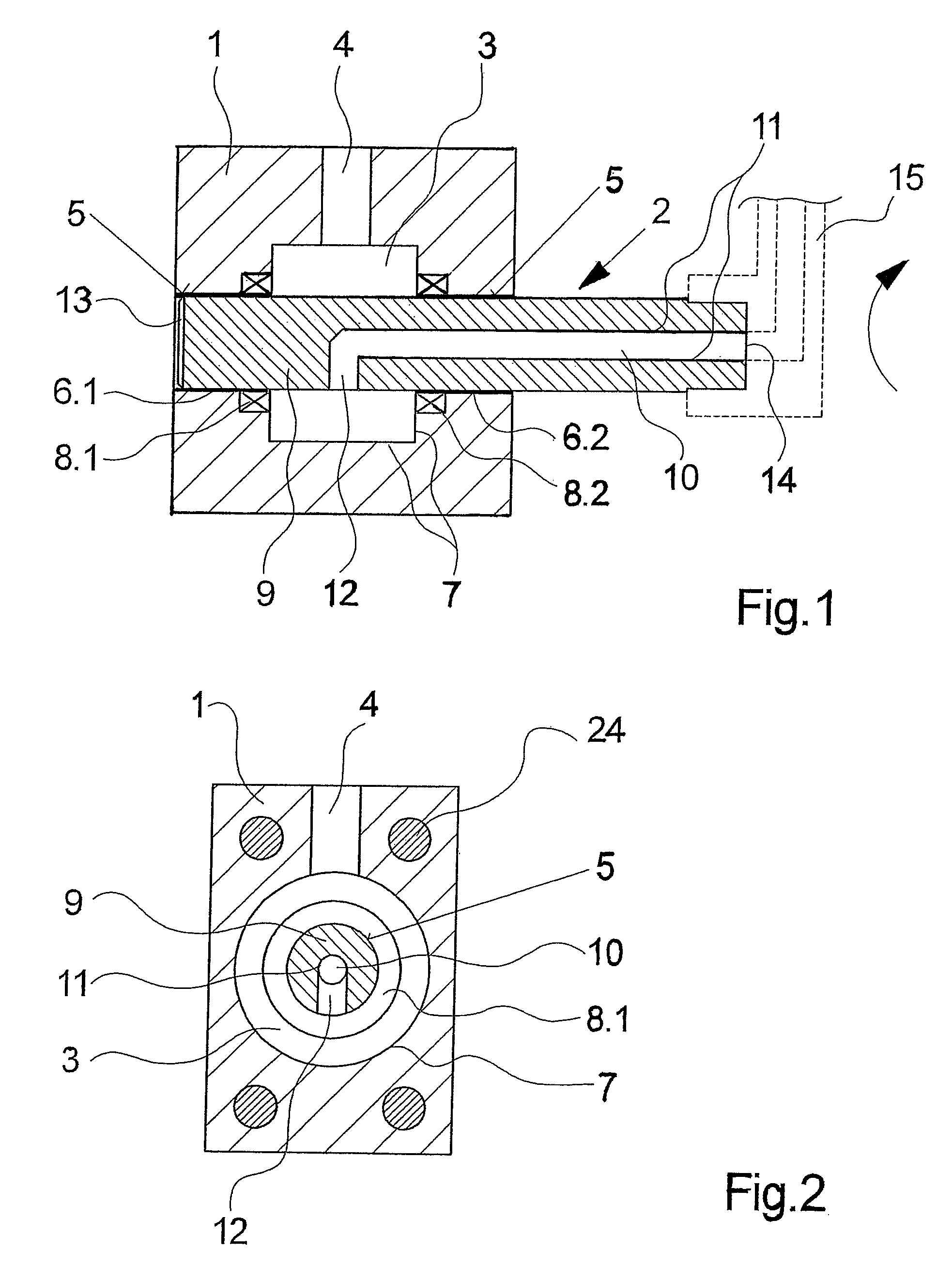
[0024]FIGS. 1 and 2 show different views of a first exemplary embodiment of a tubular rotary joint. FIG. 1 shows a longitudinal view of the exemplary embodiment, and

[0025]FIG. 2 shows a cross-sectional view thereof. The following description shall apply to both the figures unless there is explicit reference made to either of the figures.

[0026]The tubular rotary joint comprises a cuboid holder 1. In the holder 1, a distribution chamber 3 is formed, which is connected to a feeder 4. The feeder 4 is designed at the upper side of the holder 1, and is connected to a pipe section, which is not shown here.

[0027]In the holder 1 a bearing bore 5, which is directed transversely to the feeder 4, is formed in the middle region of the holder 1. The bearing bore 5 penetrates the distribution chamber 3 and the adjoining sidewalls of the holder 1. The distribution chamber 3 is formed by means of a circumferential groove 7 substantially concentrically to the bearing bore 5 within the holder 1. A con...


PUM


Abstract

The invention relates to a tubular rotary joint, in particular for conducting a polymer melt, comprising a holder and a mobile connection body, which is rotatably connected to the holder by means of one bearing end. A distribution chamber with a feeder is configured in the holder, said chamber being connected to a distribution channel that is configured in the connection body. The distribution channel in the connection body leads to a connection end, to which a pipe section can be coupled. To guarantee the flexibility of the connection body at high pressure and at high temperatures, the bearing end of the connection body is configured as a shaft journal, which is rotatably mounted in a bearing bore that penetrates the distribution chamber in the holder.

Description

CROSS-REFERENCE TO RELATED APPLICATIONS[0001]The present application is a Continuation of International Application No. PCT / EP2006 / 000071, filed Jan. 6, 2006, and which designates the U.S. The disclosure of the referenced application is incorporated herein by reference.FIELD OF THE INVENTION[0002]The invention relates to a tubular rotary joint, in particular tubular rotary joints for conducting a polymer melt.BACKGROUND OF THE INVENTION[0003]When laying and constructing pipelines, it is known to enable the rotatability of pipe sections by means of so-called tubular rotary joints. A tubular rotary joint of this type has been disclosed, for example, in DE 70 00 900 U. Here, a holder and a connection body, which is rotatably connected to the holder, interact in order to design a pipe section, which is connected to the connection body and can move in relation to the holder. Within the holder, a distribution chamber is provided, which is coupled to a distribution channel of the connectio...

Claims


Application Information

Patent Timeline
Patent Type & Authority Patents(United States)
IPC IPC(8): F16L27/00F16L27/087F16L41/08F16L41/18
CPCF16L27/087F16L27/0849
Inventor SCHUTT, GUNTERBECK, ARNOLD
Owner OERLIKON TEXTILE GMBH & CO KG
Why Eureka
Try Eureka