Pulse damper

A pulsation damper, cavity technology, used in machines/engines, liquid displacement machines, components of pumping devices for elastic fluids, etc.

Pending Publication Date: 2019-01-04
边锋机械集团有限公司
View PDF0 Cites 0 Cited by
  • Summary
  • Abstract
  • Description
  • Claims
  • Application Information

AI Technical Summary

Problems solved by technology

This type of structure can only work for diaphragm pumps with small flow and outlet pressure, and will fail when the flow is large and the outlet pressure is high

Method used


Image

  • Pulse damper
  • Pulse damper
  • Pulse damper

Examples


Embodiment Construction

[0020] Embodiments of the present invention are described in detail below, examples of which are shown in the drawings, wherein the same or similar reference numerals designate the same or similar elements or elements having the same or similar functions throughout. The embodiments described below by referring to the figures are exemplary and are intended to explain the present invention and should not be construed as limiting the present invention.

[0021] A pulse damper according to an embodiment of the present invention will be described in detail below with reference to the accompanying drawings.

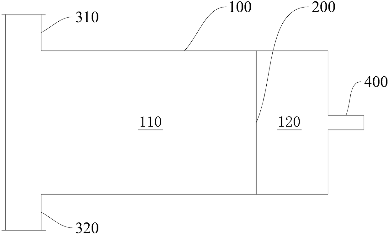
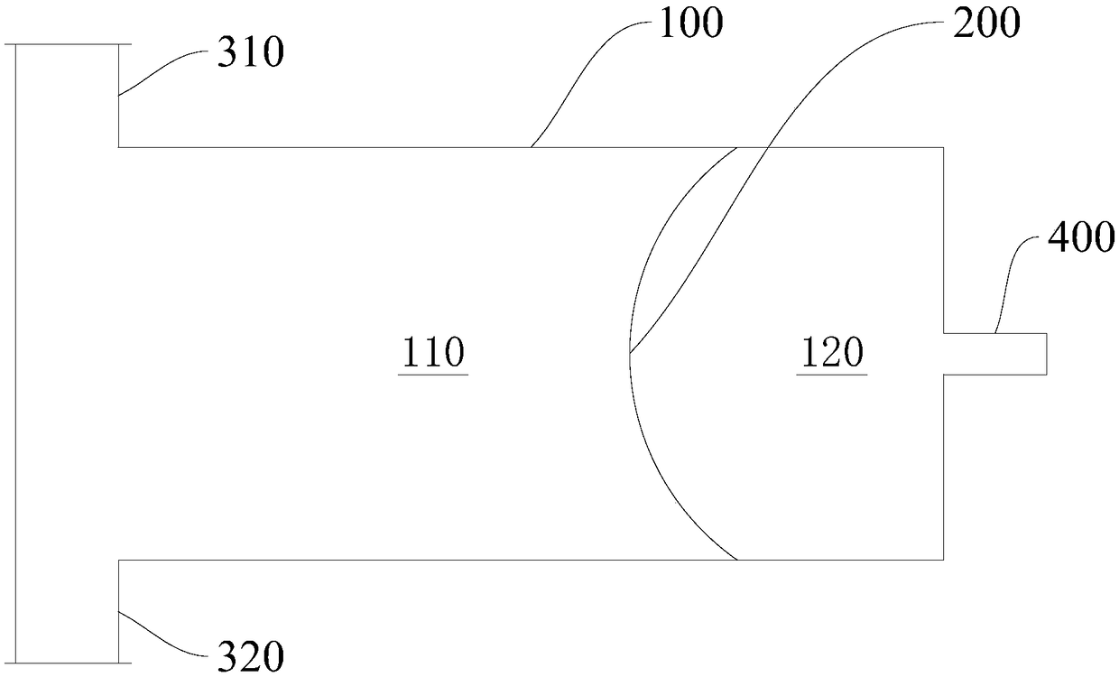
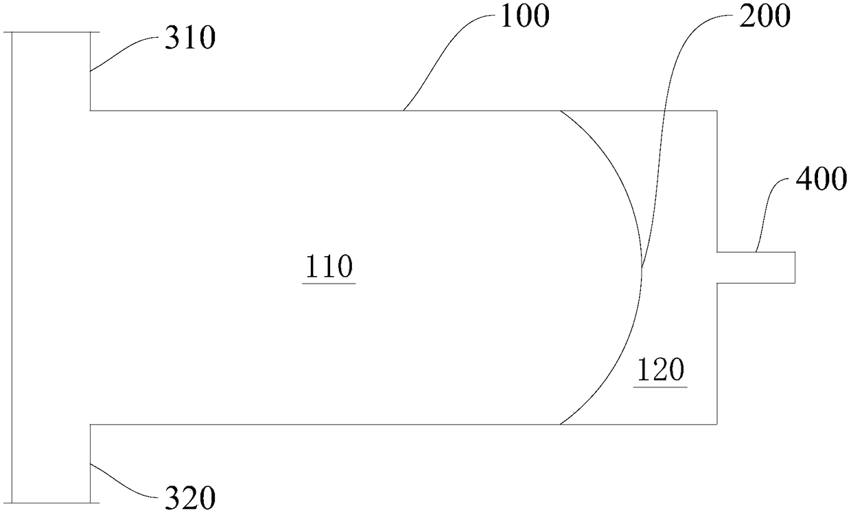
[0022] Such as Figure 1 to Figure 3 As shown, a pulsation damper according to an embodiment of the present invention includes: a body 100 , an elastic film 200 , a feed pipe 310 , a discharge pipe 320 , and an air nozzle 400 .

[0023] Specifically, a cavity is defined in the body 100 .

[0024] An elastic film 200 is provided in the cavity to partition the cavity into a fir...


PUM


Abstract

The invention provides a pulse damper. The pulse damper comprises a body, an elastic film, a feeding pipe, a discharging pipe and an air nozzle. A cavity is defined in the body. The elastic film is arranged in the cavity and divides the cavity into a first chamber and a second chamber. The feeding pipe and the discharging pipe are oppositely arranged and communicate with the first chamber. The airnozzle communicates with the second chamber. According to the pulse damper of the embodiment, when the material pressure tends to the peak pressure, the material pressure can be reduced; when the material pressure tends to the valley pressure, the material pressure can be offset; and accordingly, the material pressure is basically constant.

Description

technical field [0001] The invention relates to a pulse damper. Background technique [0002] During the transportation of liquid or solid powder materials, if the equipment for pumping materials adopts positive displacement pumps such as diaphragm pumps, continuous pulses of materials will be formed at the discharge port, and the material pulses are essentially periodic and continuous changes in the pressure of materials in the discharge pipe. . The pressure pulse will affect the outlet pipe and the outlet end. If the material velocity is too high, it will cause friction in the pipe, and even the elbow part of the pipe will be worn through by the material, resulting in pipeline damage and interruption of material delivery. When pumping paint-like materials, pulses can cause uneven spray at the outlet. When pumping powder materials, the pulse will increase the dust at the outlet and reduce the efficiency of the rear-end dust collection equipment. [0003] The existing tec...

Claims


Application Information

Patent Timeline
Patent Type & Authority Applications(China)
IPC IPC(8): F04B53/00F04B43/02
CPCF04B53/00F04B43/02
Inventor 王圣双
Owner 边锋机械集团有限公司
Why Eureka
Try Eureka