Electronic battery tester

a battery tester and electronic technology, applied in the field of storage batteries, can solve the problems that the battery testing technique may not be appropriate for the particular purpose of the battery or the configuration of multiple batteries

Inactive Publication Date: 2009-07-07
MIDTRONICS
View PDF577 Cites 76 Cited by
  • Summary
  • Abstract
  • Description
  • Claims
  • Application Information

AI Technical Summary

Benefits of technology

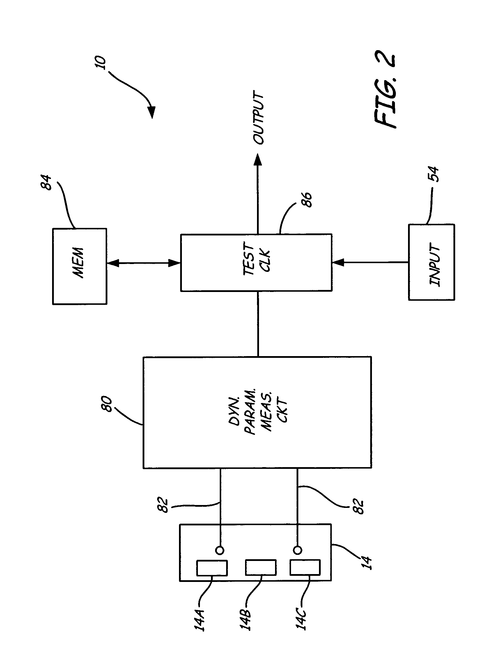
[0005]An electronic battery tester for testing a storage battery, includes a dynamic measurement circuit configured to measure at least one dynamic parameter of the battery. A memory is configured to store a plurality of test criteria and an input is configured to receive input data related to a selected test criteria. A test circuit provides an output related to battery condition as

Problems solved by technology

With the advent of accurate battery testing, it has become apparent that in some instances the battery testing t

Method used


Image

  • Electronic battery tester
  • Electronic battery tester
  • Electronic battery tester

Examples


Embodiment Construction

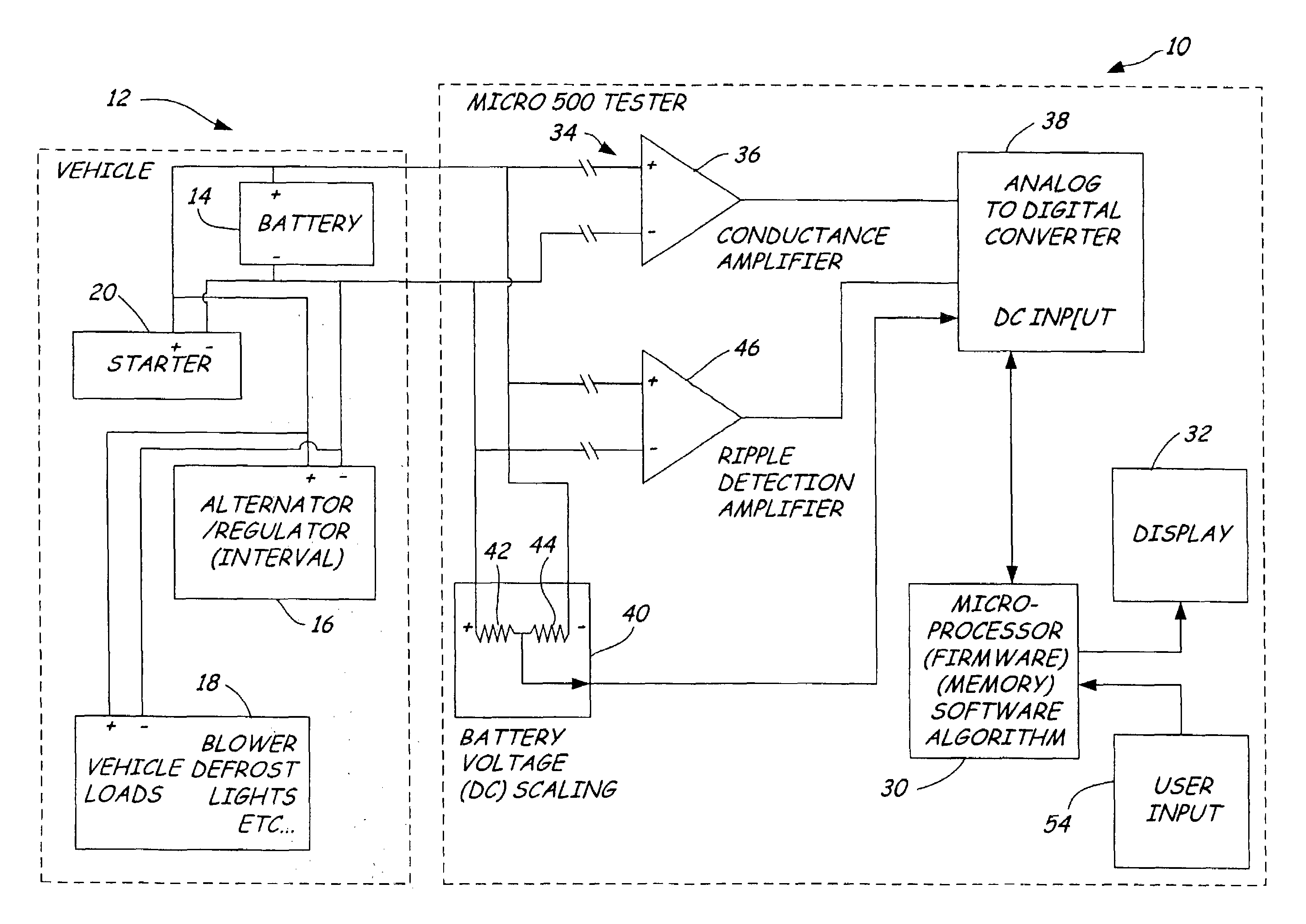
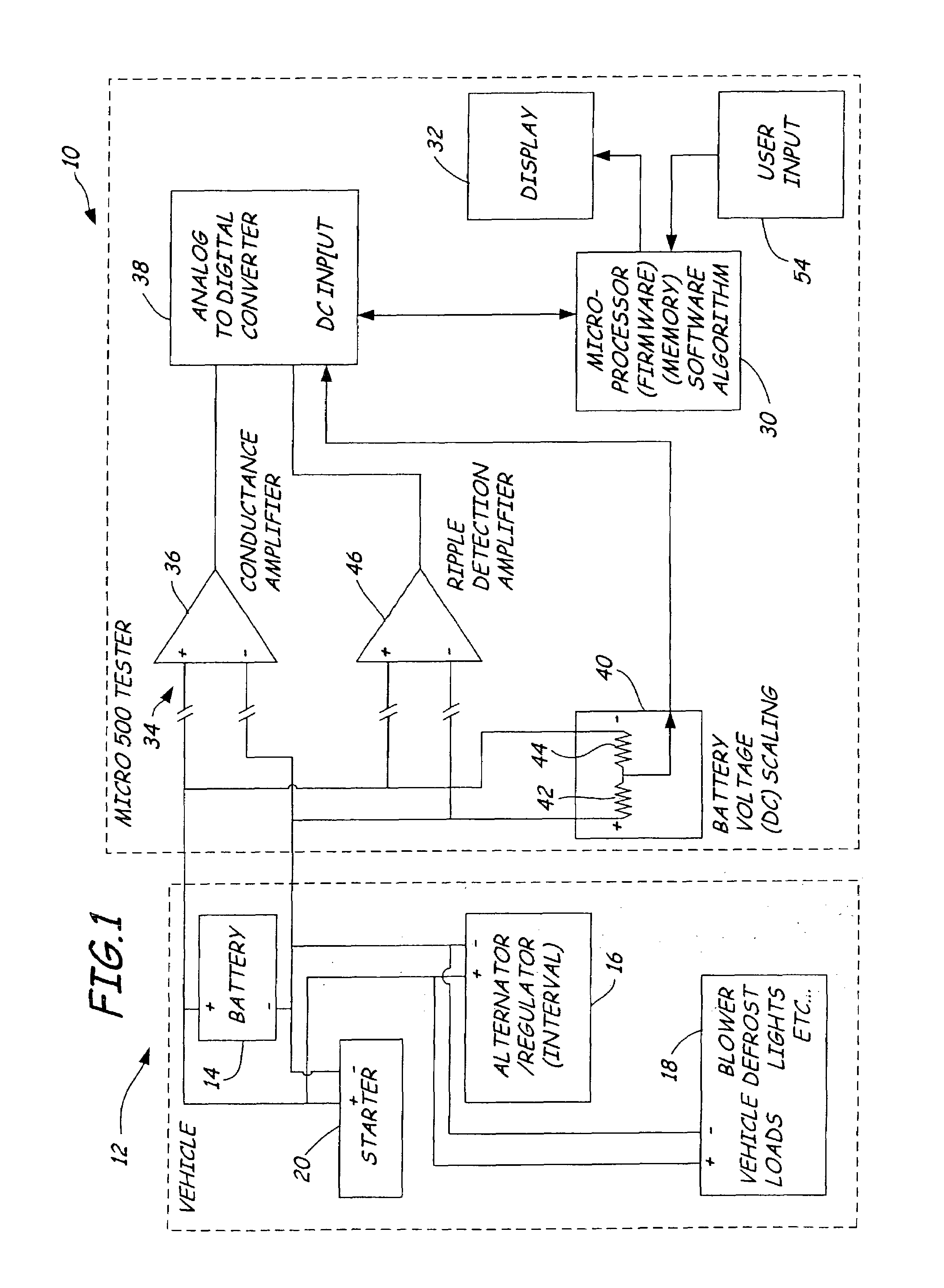
[0009]FIG. 1 is a simplified block diagram of a battery tester 10 in accordance with one embodiment of the present invention coupled to a vehicle 12. Vehicle 12 includes a battery 14 having positive and negative terminals, an alternator with internal regulator 16, various vehicle loads 18, and a starter motor 20. In operation, battery 14 provides power to starter 20 and vehicle loads 18 when the engine in vehicle 12 is not running. When the engine in vehicle 12 is running, alternator 16 is used to power vehicle loads 18 and provide a charging current to battery 14 to maintain the charge of battery 14.

[0010]Charging system tester 10 includes a microprocessor 30 which controls operation of tester 10 and provides instructions and test result information to an operator through, for example, a display 32. Tester 10 includes a battery testing section 34 which is illustrated generally as conductance amplifier 36. Section 34 operates in accordance with, for example, the conductance based ba...


PUM


Abstract

An electronic battery tester for testing a storage battery includes test circuitry configured to provide an output based upon a selected test criteria. Additionally, circuitry is provided to assist in balancing batteries used in a string of multiple batteries.

Description

[0001]This is a Divisional of application Ser. No. 09 / 703,270, filed Oct. 31, 2000 which claims priority to Provisional Application Ser. No. 60 / 163,013, filed Nov. 1, 1999 by David Vonderhaar and Michael E. Troy and entitled AUTOMOTIVE BATTERY CHARGING SYSTEM TESTER.BACKGROUND OF THE INVENTION[0002]The present invention relates to storage batteries. More specifically, the present invention relates to a battery system tester for testing storage batteries.[0003]Many attempts have been made to test storage batteries. One technique which has been pioneered by Dr. Keith S. Champlin and Midtronics, Inc. of Burr Ridge, Ill. relates to measuring the conductance of batteries to determine their condition. This technique is described in a number of United States patents, for example, U.S. Pat. No. 3,873,911, issued Mar. 25, 1975, to Champlin, entitled ELECTRONIC BATTERY TESTING DEVICE; U.S. Pat. No. 3,909,708, issued Sep. 30, 1975, to Champlin, entitled ELECTRONIC BATTERY TESTING DEVICE; U.S. ...

Claims


Application Information

Patent Timeline
IPC IPC(8): G01N27/416H02J7/00G01R31/00G01R31/36H02J7/16
CPCH02J7/163G01R31/3631G01R31/3648G01R31/3662H02J7/0004H02J7/0008H02J7/008G01R31/005G01R31/362G01R31/3641G01R31/3651G01R31/3665G01R31/3668G01R31/3675G01R31/3693G01R31/007G01R31/3647G01R31/378G01R31/367G01R31/3865G01R31/389G01R31/374G01R31/379G01R31/386G01R31/3835H02J7/00041H02J7/00036H02J7/00047H02J7/00712
Inventor VONDERHAAR, J. DAVIDBERTNESS, KEVIN I.
Owner MIDTRONICS
Why Eureka
Try Eureka