
Apparatus and method for minimizing transmission delay in a data communication system

a technology of data communication system and apparatus, applied in data switching networks, store-and-forward switching systems, multiplex communication, etc., can solve the problems of reducing the total number of transmissions, deteriorating system performance, increasing the transmission throughput, and reducing the round trip time. , to achieve the effect of reducing the transmission delay of packet data, preventing transmission delay, and preventing transmission delay

Inactive Publication Date: 2009-07-07
OTTO MANNER INNOVATIONS +2
View PDF7 Cites 24 Cited by
  • Summary
  • Abstract
  • Description
  • Claims
  • Application Information

AI Technical Summary

Benefits of technology

[0015]It is, therefore, an object of the present invention to provide an apparatus and method for preventing transmission delay using a descriptor combining technique capable of recombining.
[0016]It is another object of the present invention to provide an apparatus and method for preventing transmission delay by adding a backup queue to a transmission module.
[0017]To achieve the above and other objects, there is provided an apparatus for reducing transmission delay of packet data. The apparatus comprises a first memory having a first memory area for storing packet data to be transmitted and a second memory area for temporarily storing the packet data and for combining the packet data with subsequent packet data; a second memory for receiving and storing a copy of the packet data temporarily stored in the second memory area, and transmitting the packet data to a destination according to a link state; and a frame processor for storing a copy of the packet data stored in the second memory area in the second memory according to a state of the second memory, deleting packet data stored in the second memory area when the copy of the packet data stored in the second memory is transmitted, determining whether packet data combining is possible according to a state of the second memory area, and, if the packet data combining is possible, combining packet data stored in the first memory area with the packet data stored in the second memory area, and storing the combined packet data in the second memory.
[0018]To achieve the above and other objects, there is provided a method for reducing transmission delay occurring when transmitting packet data to a destination in a transmission module including a first memory having a first memory area for storing the packet data to be transmitted and a second memory area for backing up the first memory area, a second memory connected to a transmission link, and a frame processor. The method comprises the steps of: storing a copy of the packet data stored in the second memory area according to a state of the second memory; deleting the packet data stored in the second memory area if the copy of the packet data stored in the second memory is transmitted; determining whether packet data combining is possible according to a state of the second memory area; and if the packet data combining is possible, combining the packet data stored in the first memory area with the packet data stored in the second memory area and storing the combined packet data in the second memory.

Problems solved by technology

This process deteriorates system performance.
This technique can reduce the total number of transmissions, thereby contributing to an increase in transmission throughput and a decrease in a round trip time.
This also decreases a time delay occurring due to a protocol characteristic in which a header and a tail are added to each transmission data.
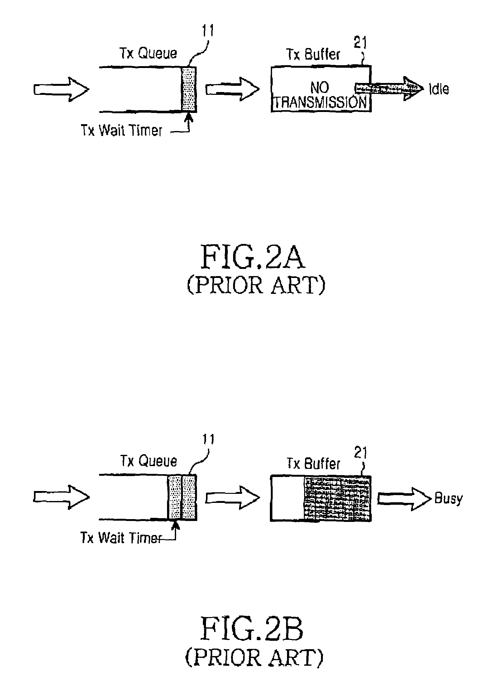
In the combining technique, even though data can be rapidly transmitted without transmission delay in view of a good channel condition, transmission data is delayed due to the transmission wait timer.
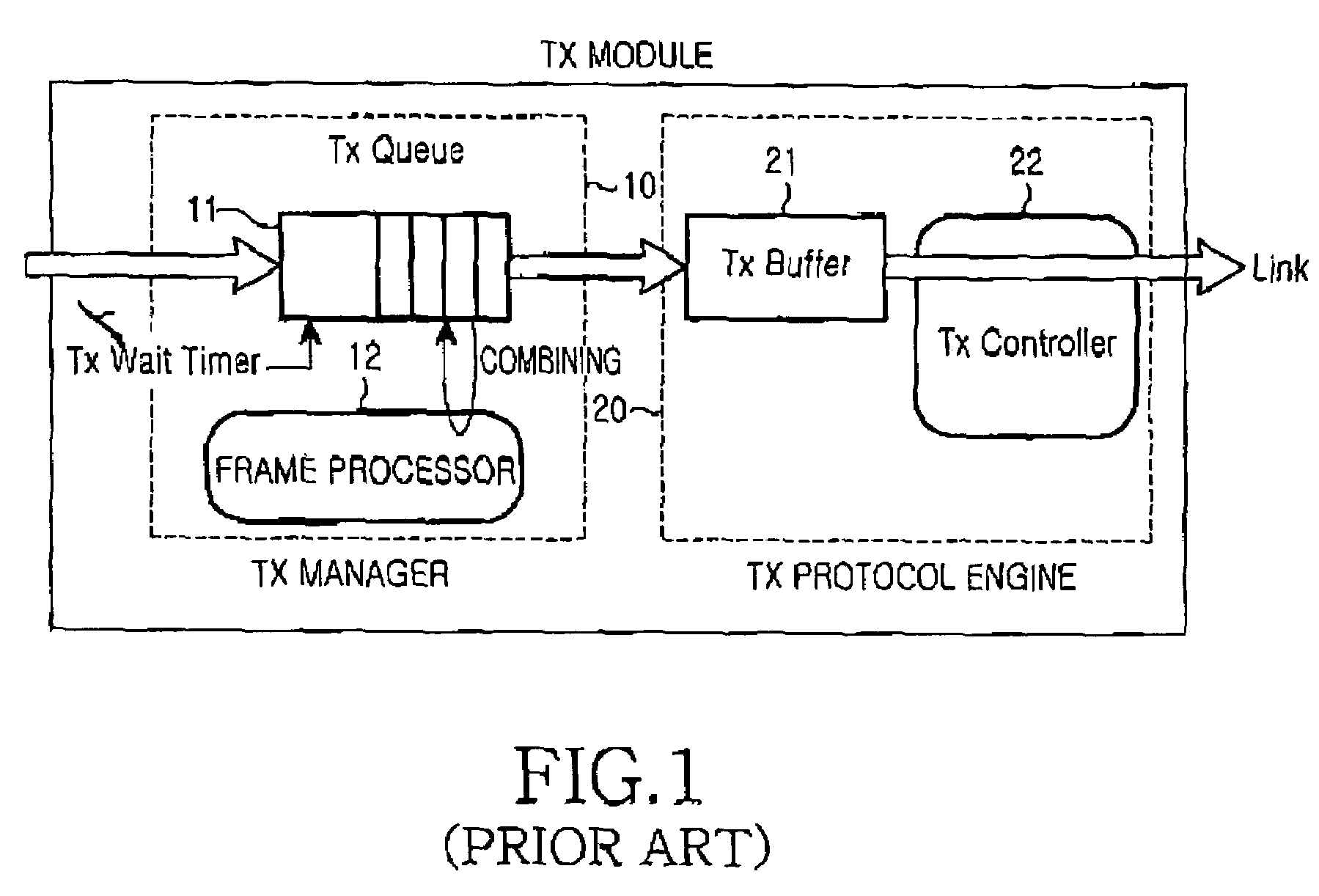
However, the conventional combining technique can combine only the data in the transmission queue 11, since the transmission manager 10 cannot consider a situation of the transmission buffer 21.

Method used


Image

  • Apparatus and method for minimizing transmission delay in a data communication system
  • Apparatus and method for minimizing transmission delay in a data communication system
  • Apparatus and method for minimizing transmission delay in a data communication system

Examples


Embodiment Construction

[0030]Several preferred embodiments of the present invention will now be described in detail with reference to the annexed drawings. In the drawings, the same or similar elements are denoted by the same reference numerals even though they are depicted in different drawings. In the following description, a detailed description of known functions and configurations incorporated herein has been omitted for clarity.

[0031]In a transmission module to which a descriptor combining technique is to be applied according to the prevention invention, a backup queue for temporarily storing packet data transmitted to a transmission buffer without being combined in a transmission queue is added to a transmission manager. The backup queue is used for recombining. Therefore, a transmission wait timer is not required. A structure of the transmission module supporting the descriptor combining technique will now be described in detail with reference to the accompanying drawings.

[0032]FIG. 3 is a block d...


PUM


Abstract

Disclosed is a method for preventing transmission delay occurring when transmitting packet data to a destination in a transmission module including a first memory having a first memory area for storing packet data to be transmitted and a second memory area for backing up the first memory area, a second memory connected to a transmission link, and a frame processor. The method comprises storing a copy of the packet data stored in the second memory area according to a state of the second memory; deleting the packet data stored in the second memory area if copy of the packet data stored in the second memory is transmitted; determining whether packet data combining is possible according to a state of the second memory area; and if the packet data combining is possible, combining the packet data stored in the first memory area with the packet data stored in the second memory area and storing the combined packet data in the second memory.

Description

PRIORITY[0001]This application claims priority under 35 U.S.C. § 119 to an application entitled “Apparatus and Method for Minimizing Transmission Delay in a Data Communication System” filed in the Korean Intellectual Property Office on May 26, 2003 and assigned Serial No. 2003-33460, the contents of which are incorporated herein by reference.BACKGROUND OF THE INVENTION[0002]1. Field of the Invention[0003]The present invention relates generally to an apparatus and method for preventing data transmission delay, and in particular, to an apparatus and method for preventing data transmission delay using a combining technique in a high-speed router and a switch.[0004]2. Description of the Related Art[0005]With the rapid increase in the number of Internet users, extensive research is being conducted to determine new methods of increasing the data rate. As a result of the research, various techniques for saving transmission resources and increasing throughput by reducing the overhead of tra...

Claims


Application Information

Patent Timeline
Patent Type & Authority Patents(United States)
IPC IPC(8): H04L12/28H04J3/24H04L12/54H04L12/861H04L29/06
CPCH04L49/90H04L69/04H04L49/9094
Inventor HWANG, HYO-SUNCHOI, SUNG-HYUNJANG, KYUNG-HUNKIM, YOUNG-SOO
Owner OTTO MANNER INNOVATIONS
Learn More