
Wireless sensor network system

Active Publication Date: 2014-07-24
NTT MOBILE COMM NETWORK INC
View PDF3 Cites 9 Cited by
  • Summary
  • Abstract
  • Description
  • Claims
  • Application Information

AI Technical Summary

Benefits of technology

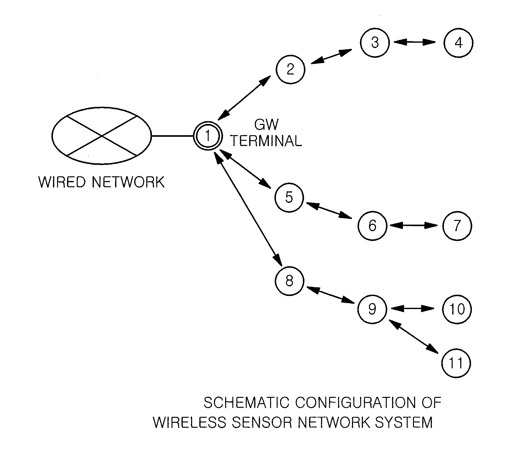
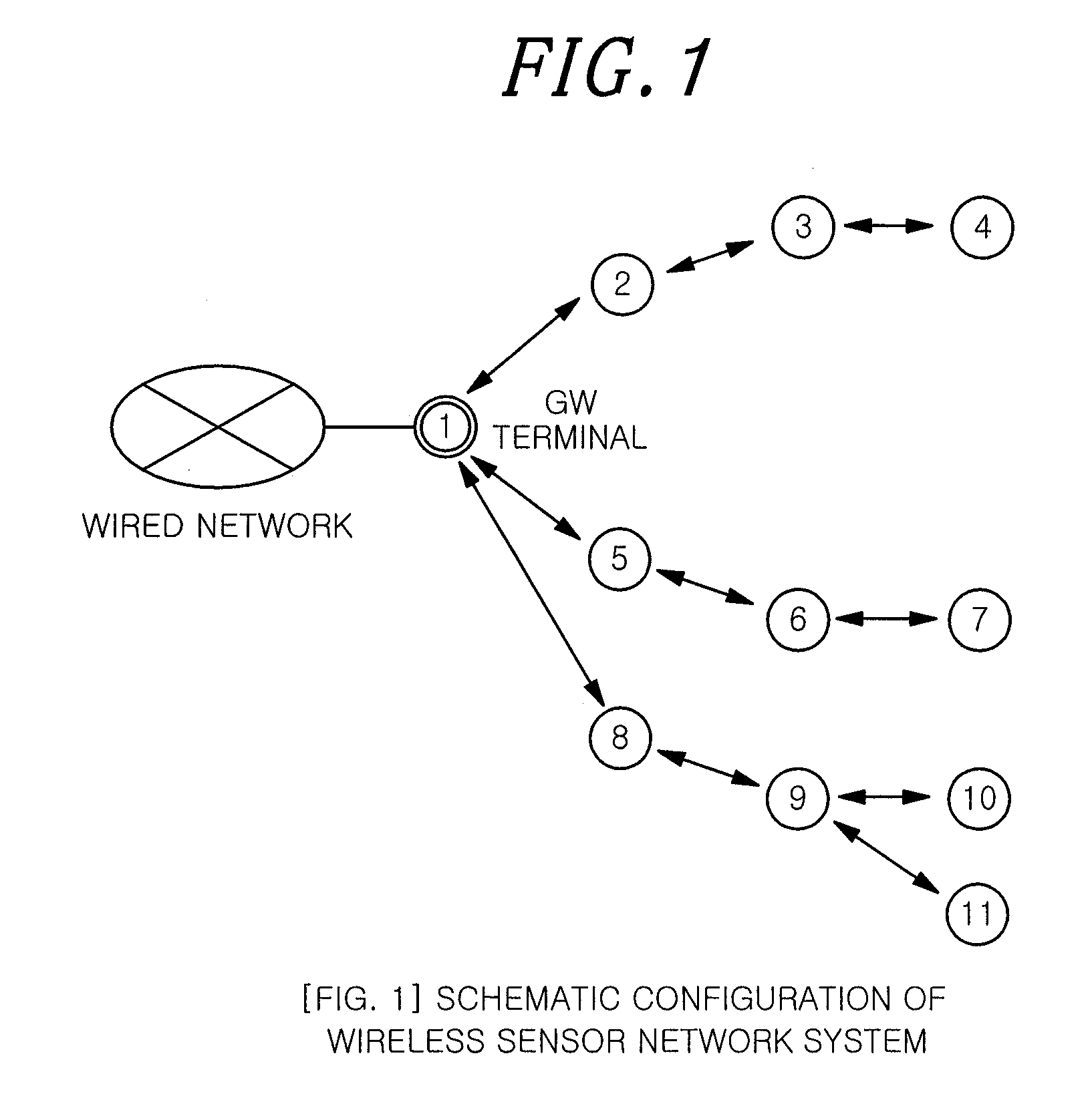
The wireless sensor network system described in this patent allows for efficient communication between sensor terminals and a management terminal. When an additional sensor terminal joins the network, it sends a join request to the management terminal. The management terminal calculates the traffic load on the route through which the join request is received and determines if it is within the permissible ranges. If so, it reconstructs the communication route by sending an instruction to the additional sensor terminal to make direct connection to the management terminal or a specific node with a low traffic load at a higher transmission power. This prevents data transfer delay and increases efficiency of the entire network. Both the sensor terminal and the management terminal determine the proper transmission power and access destination based on the instruction, preventing an increase in traffic load and concentration of load on specific nodes. Overall, this system allows for proper communication and efficient operation.

Problems solved by technology

However, in the conventional wireless sensor network system, depending on arrangement of sensor terminals, transmission delay may be increased with an increase in the number of hops and the traffic load may be concentrated on a specific sensor terminal.

Method used


Image

  • Wireless sensor network system
  • Wireless sensor network system
  • Wireless sensor network system

Examples


Embodiment Construction

[0033]Embodiments of the present invention will be described with reference to the drawings.

Outline of Embodiments

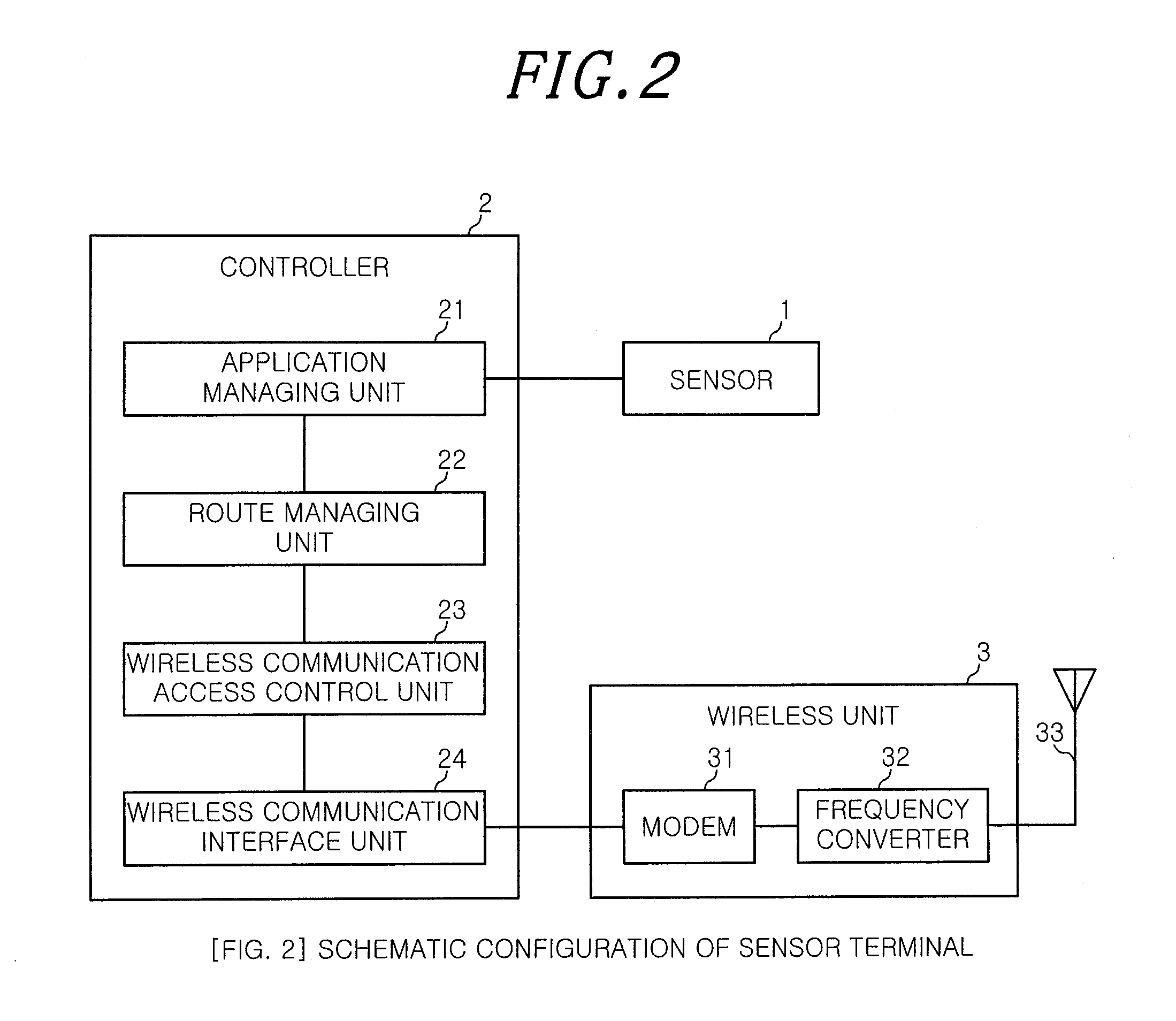
[0034]A wireless sensor network system according to embodiments of the present invention includes sensor terminals and a GW terminal (management terminal), each of the sensor terminals and the GW terminal having a low power mode of about 10 mW for performing ad hoc communication and a high power mode for performing a wide range communication at a higher power. When a sensor terminal newly joins a network, the sensor terminal accesses the GW terminal via adjacent sensor terminals at the low power mode, and the GW terminal calculates the number of hops of the corresponding sensor terminal in a reception route and a traffic load of each node on the reception route. If both of the number of hops and the traffic load are within their respective permissible ranges, the GW terminal determines a communication route of the corresponding newly joining sensor terminal in the recept...


PUM


Abstract

A wireless sensor network system includes: sensor terminals and a management terminal. A sensor terminal sends a join request at a first transmission power; and the management terminal calculates the traffic load of nodes on the reception path of the join request. If the number of hops and the traffic load are both within respective permissible ranges, the management terminal sets the reception path as the communication route of the sensor terminal. If the number of hops and / or the load is not within the permissible rage, the management terminal reconstructs the communication path by outputting an instruction to the sensor terminal to make direct connection to the management terminal or a specified node with a low traffic load, at a second transmission power greater than the first transmission power. When receiving the instruction, the sensor terminal transmits to the management terminal or the specified node at the second transmission power.

Description

FIELD OF THE INVENTION[0001]The present invention relates to a wireless sensor network system and more particularly, to a wireless sensor network system which is capable of reducing delay time by preventing increase in a traffic amount of an overall system and capable of efficiently operating the system by preventing concentration of a traffic load on a specified terminal.BACKGROUND OF THE INVENTION[0002]1. Description of Prior Art[0003]A wireless sensor network system has been used as a system which includes a plurality of sensor terminals and collects data of equipment monitoring and data of power, gas and water usage in a factory or a plant through wireless communication. In such a wireless sensor network system, in many cases, a sensor terminal may access a server or the like via a wired network in order to manage data collected from sensor terminals. A sensor terminal, which has the function of access the wired network and arranges and transmits data from a sensor terminal with...

Claims


Application Information

Patent Timeline
IPC IPC(8): H04W28/02H04W40/04H04W84/18H04W4/70
CPCH04W28/021H04W40/04H04W84/18H04W40/12H04W40/22H04L67/1097H04W4/70Y02D30/70H04W72/21H04W72/23
Inventor ISHIZAKI, MASAYUKI
Owner NTT MOBILE COMM NETWORK INC
Learn More