
Iron-type golf clubs

a golf club and iron-type technology, applied in the field of golf clubs, can solve the problems of difficult to achieve the fine tuning of the center of gravity and moment of inertia properties, and the difficulty of hitting consistently well by the average golfer

Active Publication Date: 2009-07-14
ACUSHNET CO
View PDF27 Cites 113 Cited by
  • Summary
  • Abstract
  • Description
  • Claims
  • Application Information

AI Technical Summary

Benefits of technology

The present invention relates to a set of golf clubs that includes long and short irons with different inserts to achieve different performance characteristics. The iron-type golf club head includes a forged body with a hitting face and a rear flange, and an insert made of a second material with lower density than the first material. The method of customizing a golf club head involves testing the head with different mass control inserts and securing one of them to the head. The technical effects of the invention include improved performance and customization options for golf club heads.

Problems solved by technology

Therefore, the club heads of the long irons have a smaller face surface area than the short irons and are typically more difficult for the average golfer to hit consistently well.
One challenge for the golf club designer when maximizing the size of the club head is to maintain a desirable and effective overall weight of the golf club.
For example, if the club head of a three iron is increased in size and weight, the club may become more difficult for the average golfer to swing properly.
Fine tuning the center of gravity and moment of inertia properties is difficult to achieve while simultaneously attempting to capture within a set of clubs a continuous aesthetic look and feel.
Additionally, if different clubs from different manufacturers are used, any given club within a piecemeal set could have the correct playing standards but lack the desired feel for a golfer.

Method used


Image

  • Iron-type golf clubs
  • Iron-type golf clubs
  • Iron-type golf clubs

Examples


Embodiment Construction

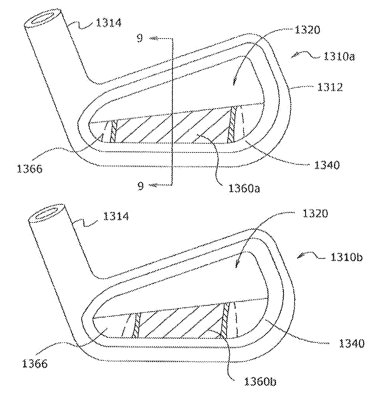
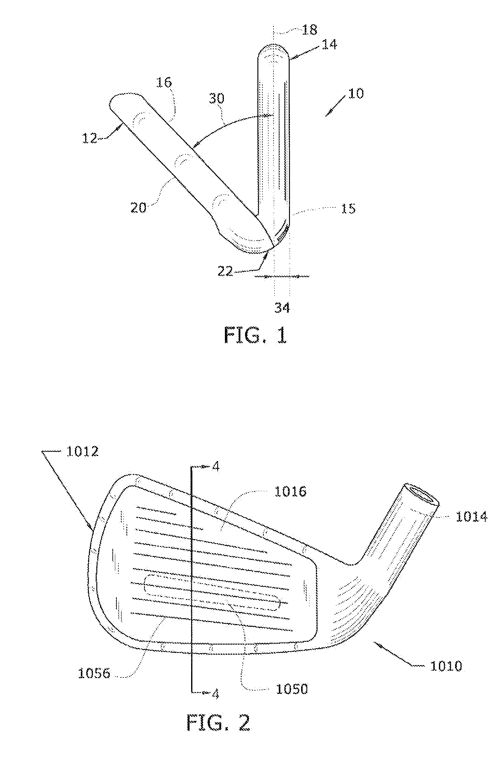
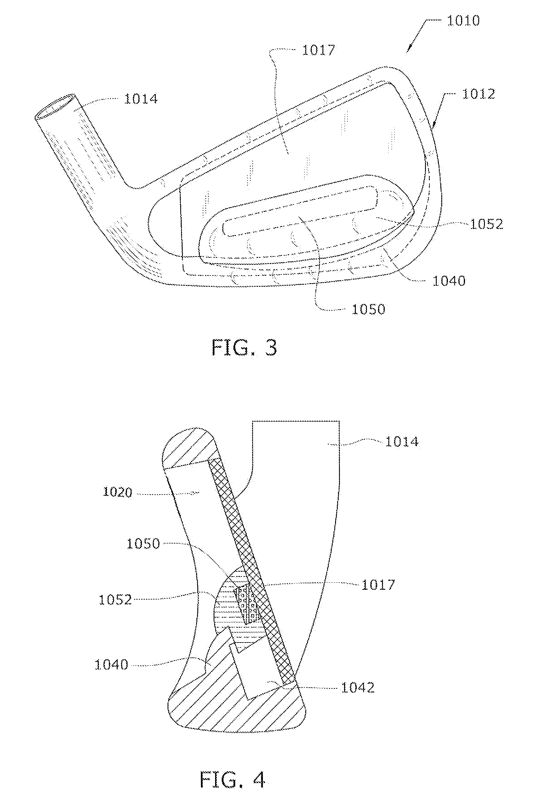
[0035]As illustrated in the accompanying drawings and discussed in detail below, the present invention is directed to a set of iron-type golf clubs. For the purposes of illustration, FIG. 1 shows a reference iron-type club head 10 for defining various design parameters for the present invention. These design parameters for the clubs are chosen such that the parameters progress through the set from the long irons to the short irons in a pre-determined fashion. Club head 10 is attached to a shaft (not shown) in any manner known in the art.

[0036]Club head 10 includes, generally, a body 12 and a hosel 14. Body 12 includes a striking or hitting face 16 and a rear face 20. Body 12 is attached to hosel 14 at an angle, such that a loft angle 30 is defined between a hosel center line 18 and hitting face 16. Further, the relative configuration of body 12 and hosel 14 results in an offset 34 between the leading edge 22 of the base of the hitting face and the forward-most point 15 of the hosel....


PUM

PropertyMeasurementUnit
length L3aaaaaaaaaa
length L3aaaaaaaaaa
angleaaaaaaaaaa

Abstract

A set of iron-type golf clubs includes long, mid- and short irons with channel back configurations and a mass control insert. The mass of the insert is systematically varied through the set such that the mass distribution properties of the set may be systematically varied while retaining a continuous look and feel through the set. The mass of the insert is varied by altering the volume or the density of the insert through the set. Additional design parameters for the set may also be systematically varied through the set, such as groove type and depth, loft angle, cavity volume, hitting face roughness, and sole width. In one embodiment, the mass control insert comprises a dense insert and a lightweight cover. The density of the dense insert can be easily varied to change the mass distribution properties of the club head. One application of the mass control insert is to provide customization of the club head at the point of sale or distribution.

Description

CROSS-REFERENCE TO RELATED APPLICATION[0001]The present application is a continuation-in-part of U.S. application Ser. No. 11 / 193,745 filed on Jul. 29, 2005, now U.S. Pat. No. 7,232,377, which is a continuation-in-part of U.S. Application Ser. No. 11 / 105,631 filed on Apr. 14, 2005, now U.S. Pat. No. 7,186,187, which are both incorporated herein by reference in their entireties.FIELD OF THE INVENTION[0002]This invention generally relates to golf clubs, and, more particularly, to iron clubs.BACKGROUND OF THE INVENTION[0003]Individual iron club heads in a set typically increase progressively in face surface area and weight as the clubs progress from the long irons to the short irons and wedges. Therefore, the club heads of the long irons have a smaller face surface area than the short irons and are typically more difficult for the average golfer to hit consistently well. For conventional club heads, this arises at least in part due to the smaller sweet spot of the corresponding smaller...

Claims


Application Information

Patent Timeline
Patent Type & Authority Patents(United States)
IPC IPC(8): A63B53/04
CPCA63B53/047A63B59/0092A63B2053/005A63B2053/0416Y10T29/49764A63B2053/0458A63B2053/0491A63B2053/042A63B2053/0445A63B53/0475A63B60/02A63B60/54A63B53/005A63B53/0408A63B53/0412A63B53/0416A63B53/042A63B53/00A63B53/0445A63B53/0458
Inventor GILBERT, PETER J.PETTIBONE, BRUCE R.BURNETT, MICHAEL SCOTTKAYS, CHRISTOPHER R.DIAZ, TOMAS
Owner ACUSHNET CO
Learn More