

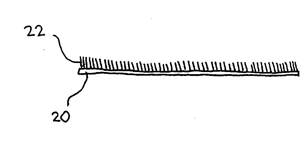
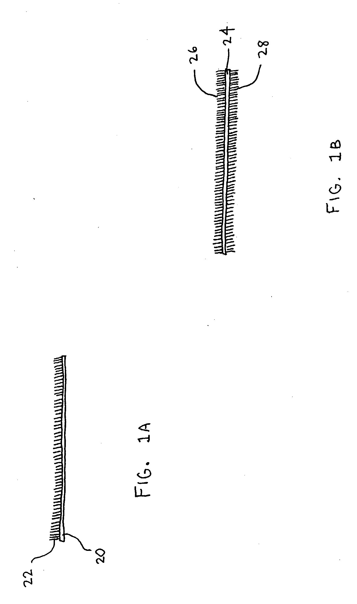
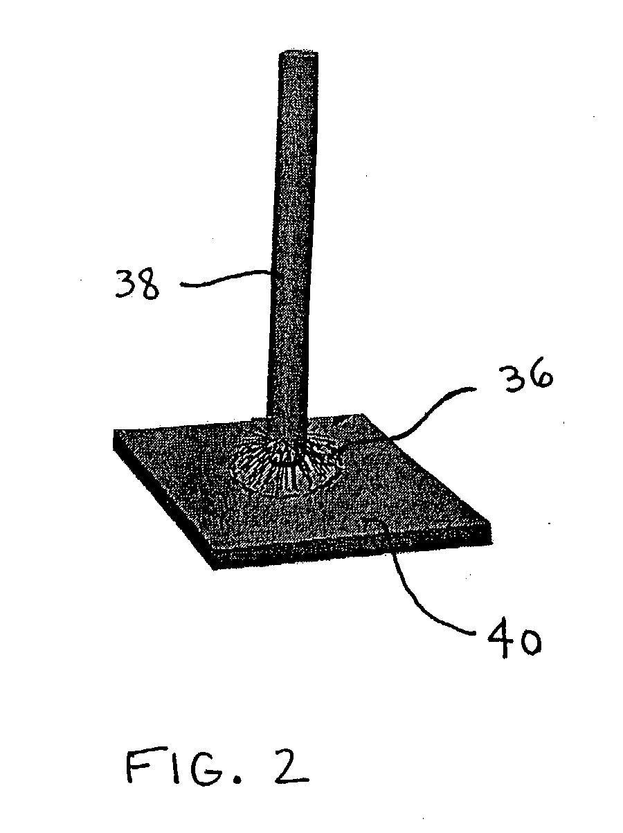
Fiber adhesive material
a technology of adhesive materials and fibers, applied in the direction of laminated elements, semiconductor/solid-state device details, broidering machines, etc., can solve the problems of limiting the overall performance of the thermal control system, requiring special fixation for attaching, and not being reusable or easily removabl
- Summary
- Abstract
- Description
- Claims
- Application Information
AI Technical Summary
Benefits of technology
Problems solved by technology
Method used
Image

Examples
Embodiment Construction
[0064] Pitch carbon fiber gasket sample cs7-144 was processed in the PE-HF CVD reactor under the conditions listed in Table 1
1TABLE 1 PE-HF CVD deposition conditions of pitch fiber gasket sample Sample# cs7-144 Mounting Lying flat on anode conditions Plasma power 160 W HF power 300 W Max temperature 527.degree. C. Plasma etch time 12 min Deposition time 5 min Hydrocarbon gas Acetylene Mass gain 4.6 mg (5 %) Resulting deposit Heavy, bottom side
[0065] After the chamber cooled, the sample was removed and examined under the microscope. The bottom of Sample cs7-144 was covered with carbon deposit that was visible under the optical microscope. The 90.5 mg sample had gained 4.6 mg, which corresponds to a 4 micron-thick, uniform layer of carbon over one surface. Some areas displayed thicker deposits than others did. The variation may reflect variation in local temperature, hydrocarbon concentration, and / or catalyst microstructure.
[0066] FIG. 5 is a 250.times. SEM image of a pitch carbon fib...
PUM
| Property | Measurement | Unit |
|---|---|---|
| diameter | aaaaa | aaaaa |
| diameters | aaaaa | aaaaa |
| diameter | aaaaa | aaaaa |
Abstract
Description
Claims
Application Information