System and method for automatically securing a motor control center

a technology of automatic securing and control center, which is applied in the direction of substations, casings/cabinets/drawer details, coupling device connections, etc., can solve the problems of affecting the operation of the mcc, affecting the accuracy of the measurement, and being awkward to work in

Active Publication Date: 2009-07-14
ROCKWELL AUTOMATION TECH
View PDF21 Cites 37 Cited by
  • Summary
  • Abstract
  • Description
  • Claims
  • Application Information

AI Technical Summary

Problems solved by technology

Unfortunately, the MCC typically contains high voltages that can be hazardous during operation of the MCC.
The special safety precautions often entail the use of personal protective equipment, which may be awkward to work in and hamper the taking of measurements.

Method used


Image

  • System and method for automatically securing a motor control center
  • System and method for automatically securing a motor control center
  • System and method for automatically securing a motor control center

Examples


Embodiment Construction

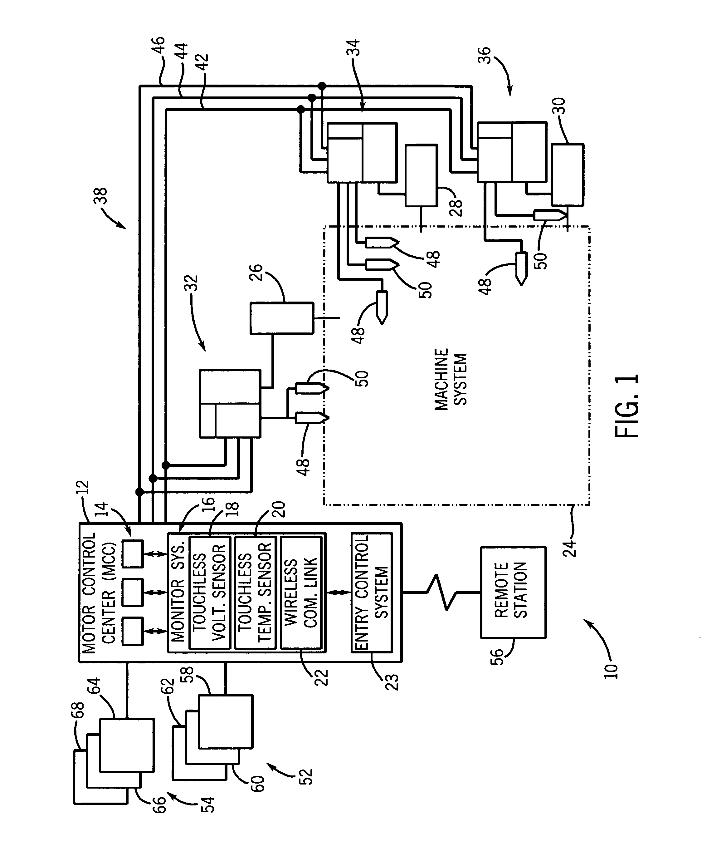
[0012]Turning to the figures, FIG. 1 is a diagram illustrating an exemplary system 10 having a power distribution center, e.g., a motor control center (MCC) 12, with various control circuitry and components 14 and a monitoring system 16. As discussed in detail below, the monitoring system 16 includes one or more touchless voltage sensors 18, one or more touchless temperature sensors 20, and one or more wireless communication links 22. In other words, the touchless sensors 18 and 20 do not directly contact or electrically connect with the wires, components, and so forth. In some embodiments, the touchless sensors 18 and 20 are standalone units that have their own wireless communication links 22 (e.g., transceivers), such that the sensors are completely electrically isolated from other components. In other embodiments, the touchless sensors 18 and 22 are electrically isolated by using optical cables, which lead to the monitoring system 16. Further embodiments employ opto-isolators or ...


PUM


Abstract

A system, in one embodiment, includes a power distribution center having an enclosure with an access door configured to move between a closed position and an open position. The system also includes a monitoring system configured to monitor operational parameters inside the enclosure. Also, the system includes an entry control system coupled to the monitoring system, wherein the entry control system is configured to lock the access door if the operation parameters are indicative of a potentially hazardous condition inside the enclosure.

Description

BACKGROUND[0001]The present invention relates generally to the field of packaged electrical systems. More particularly, the invention relates to a system and method for securing a motor control center (MCC).[0002]A range of applications exist for packaged electrical and electronic components, particularly power electronic components such as those used to power loads in industrial applications. In one type of packaged system, typically referred to as a motor control center (MCC), various switch gear, control devices, protective circuit devices, programmable logic controllers, motor drives, and so forth are housed in a large enclosure that may be subdivided into compartments. The enclosure is supplied with power by power buses that extend generally in a plane toward the rear of the enclosure. The individual compartments typically house associated circuitry that may be withdrawn from the enclosure for servicing and replacement. Compartmentalizing such systems greatly enhances the abili...

Claims


Application Information

Patent Timeline
Patent Type & Authority Patents(United States)
IPC IPC(8): H05K5/02
CPCH02B13/025H02B1/36H02B13/065
Inventor BRANDT, DAVID D.JENSEN, DAVID L.
Owner ROCKWELL AUTOMATION TECH
Why Eureka
Try Eureka