Bidirectional forwarding detection

a detection and bidirectional technology, applied in the field of communication system detection, can solve the problem that the component in the particular bidirectional path to the neighboring system is assumed to have failed, and achieve the effect of rapid detection of failures

Active Publication Date: 2009-07-14
JUMIPER NETWORKS INC +1
View PDF16 Cites 87 Cited by
  • Summary
  • Abstract
  • Description
  • Claims
  • Application Information

AI Technical Summary

Benefits of technology

[0015]In at least one embodiment consistent with the invention, each system participating in a BFD session estimates how quickly it can send and receive BFD packets. These estimates are used to determine mutually agreeable parameters concerning how fast BFD packets are to be transmitted and / or how fast a detection of failure will occur. These estimates can be modified in real time, for example to adapt to unusual situations. Thus, such an embodiment consistent with the invention allows for fast systems on a shared medium with a slow system to more rapidly detect failures between the fast systems, while allowing the slow system to participate to the best of its ability.

Problems solved by technology

If a system stops receiving BFD packets for a sufficient time, some component in that particular bidirectional path to the neighboring system is assumed to have failed.

Method used


Image

  • Bidirectional forwarding detection
  • Bidirectional forwarding detection
  • Bidirectional forwarding detection

Examples


Embodiment Construction

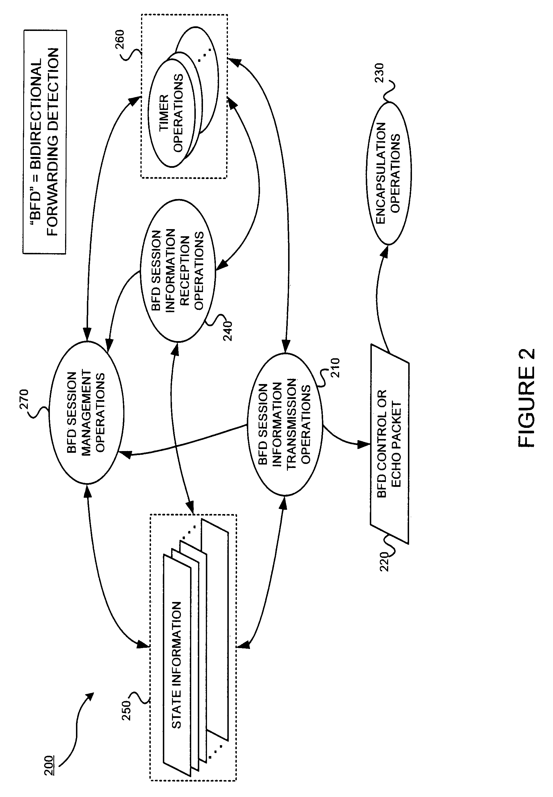
[0028]An exemplary environment, in which embodiments consistent with the invention may operate, is introduced with reference to FIG. 1 in § 4.1. Then exemplary operations of embodiments consistent with the invention, as well as exemplary methods, data structures and apparatus, are introduced with reference to FIGS. 2-11 in § 4.2.

§ 4.1 Exemplary Environment

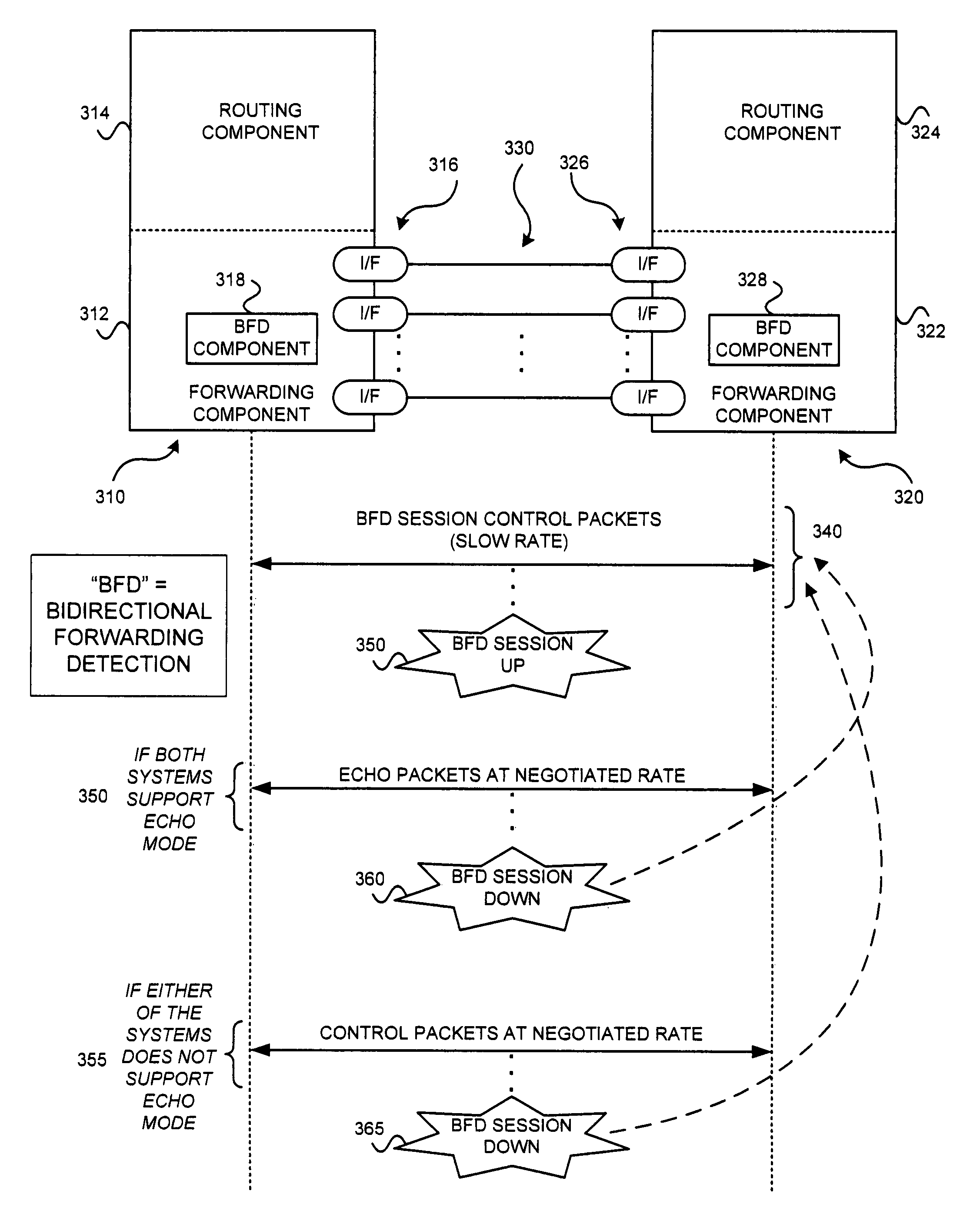
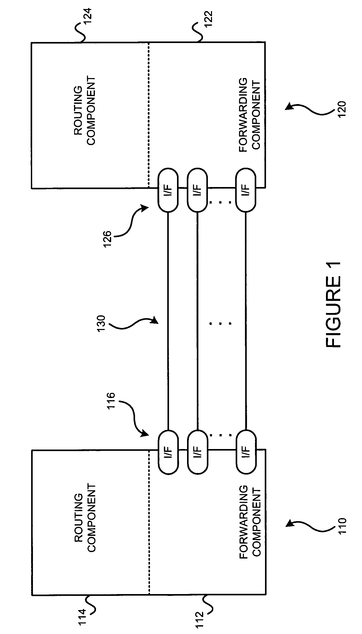
[0029]FIG. 1 illustrates two systems 110 and 120 coupled via communications links 130. The links may be physical links or “wireless” links. The systems 110,120 may be routers for example. If the systems 110,120 are routers, each may include a routing component 114,124 and a forwarding component 112,122. Each system 110,120 includes one or more interfaces 116,126 that terminate one or more communications links 130. A failure in the so-called “data forwarding plane” may occur in one of the forwarding components 112,122, one of the interfaces 116,126, and / or one of the links 130.

[0030]The invention can detect such failures in communic...


PUM


Abstract

A protocol for detecting faults in a bidirectional path between two forwarding engines, where parts of the bidirectional path checked may include interfaces, one or more data links, and to the extent possible the forwarding engines themselves, with potentially very low latency. The protocol may operate independently of media, data protocols, and routing protocols.

Description

§ 0. BENEFIT OF EARLIER FILED PROVISIONAL APPLICATION[0001]This application claims the benefit of U.S. Provisional Application No. 60 / 467,276, entitled “BIDIRECTIONAL FORWARDING DETECTION,” filed on May 2, 2003, and listing Dave Katz and Dave Ward as inventors. That Provisional Application is incorporated herein by reference. The invention is not limited to the particular embodiments described in that Provisional Application.§ 1. BACKGROUND OF THE INVENTION[0002]§ 1.1 Field of the Invention[0003]The invention concerns detecting failures in communications systems. In particular, the invention concerns detecting failures, such as forwarding engine failures, interface failures, and / or link failures, of a data forwarding path between and including two data forwarding devices, such as routers for example.[0004]§1.2 Related Art[0005]The description of art in this section is not an admission that such art is prior art to the invention.[0006]An increasingly important feature of networking e...

Claims


Application Information

Patent Timeline
Patent Type & Authority Patents(United States)
IPC IPC(8): H04L1/00H04L12/26
CPCH04L12/2697H04L45/28H04L45/22H04L43/50
Inventor KATZ, DAVIDWARD, DAVID D.
Owner JUMIPER NETWORKS INC
Why Eureka
Try Eureka