Spring arm and body support

a spring arm and body technology, applied in the field of body support, can solve the problems of extreme progression in the lower movement range of the spring arm, the influence of the camera guidance,

Inactive Publication Date: 2009-07-21
CAMERA DYNAMICS
View PDF26 Cites 41 Cited by
  • Summary
  • Abstract
  • Description
  • Claims
  • Application Information

AI Technical Summary

Benefits of technology

[0014]Thus the cameraman can adjust the energy storage mechanism's adjustable pivot point in any position of the parallelogram guide such that the energy storage mechanism exactly compensates the weight of the camera to be guided.
[0016]Due to the innovative adjustability of the energy storage mechanism's pivot points it is also possible to optimize any kinematics of a parallelogram which have been calculated less than optimally. In this way it is possible to absorb production errors and tolerances.

Problems solved by technology

The cameraman has to absorb this differential force, which leads of course to impairment of the camera's guidance: often the spring arm's optimum performance is only generated in the horizontal position whilst in its very upwardly deflected position the spring arm only applies an insufficient force.
An extreme progression in the spring arm's lower movement range is also problematic.

Method used


Image

  • Spring arm and body support
  • Spring arm and body support
  • Spring arm and body support

Examples


Embodiment Construction

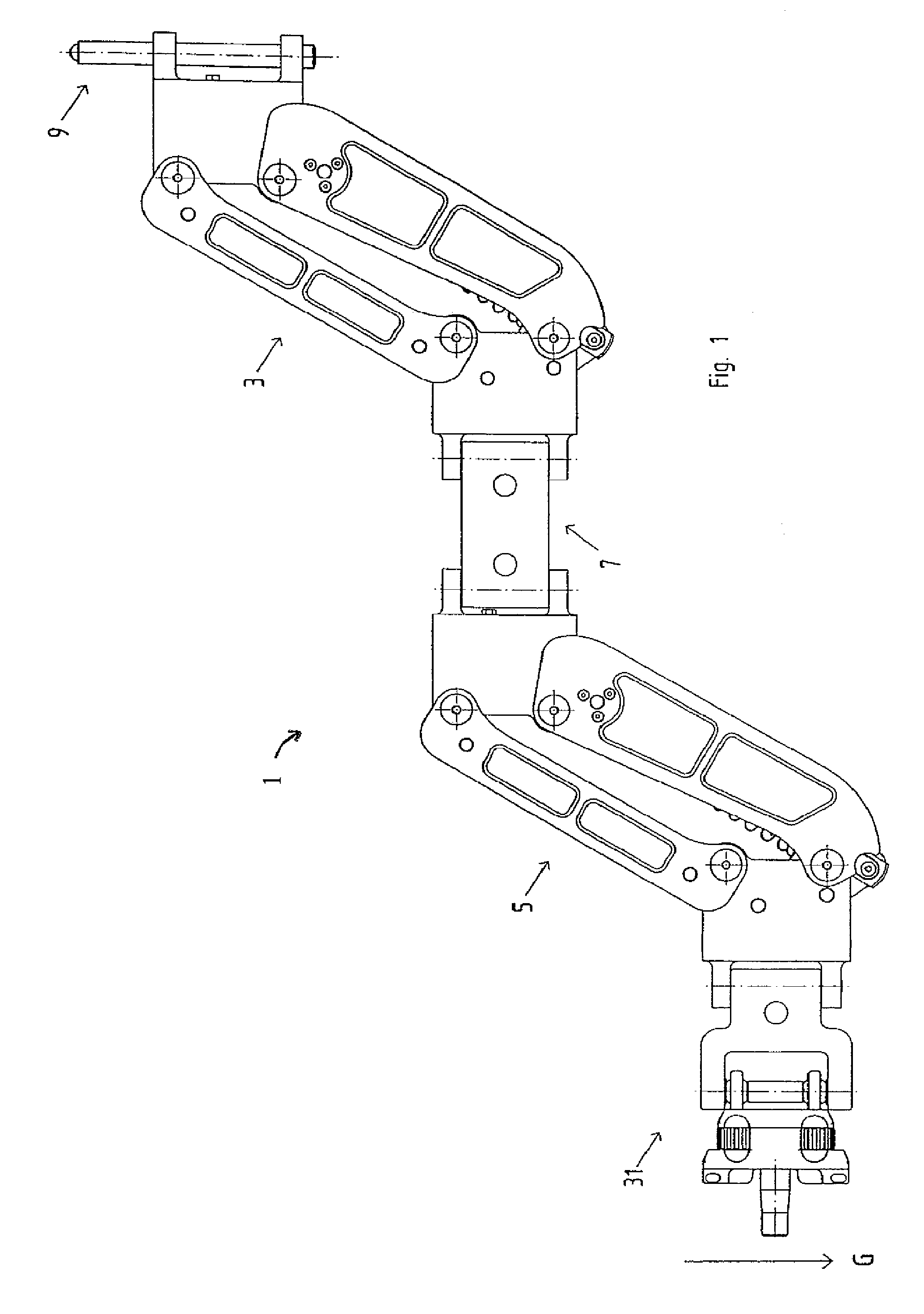
[0033]A first preferred embodiment of a spring arm according to the invention will now be described with reference to FIGS. 1 to 5 of the drawings.

[0034]FIG. 1 shows an overall view of a spring arm 1 according to the invention. This consists primarily of two parallelogram guides 3 and 5 which are linked to one another by way of coupling element 7 and which will be discussed in greater detail at a later point. On its first end, spring arm 1 has a pin 9 by way of which it can be pivotably attached to a belt or harness of the cameraman. A holder 31 on the other end of the spring arm serves for attachment of the camera to be guided.

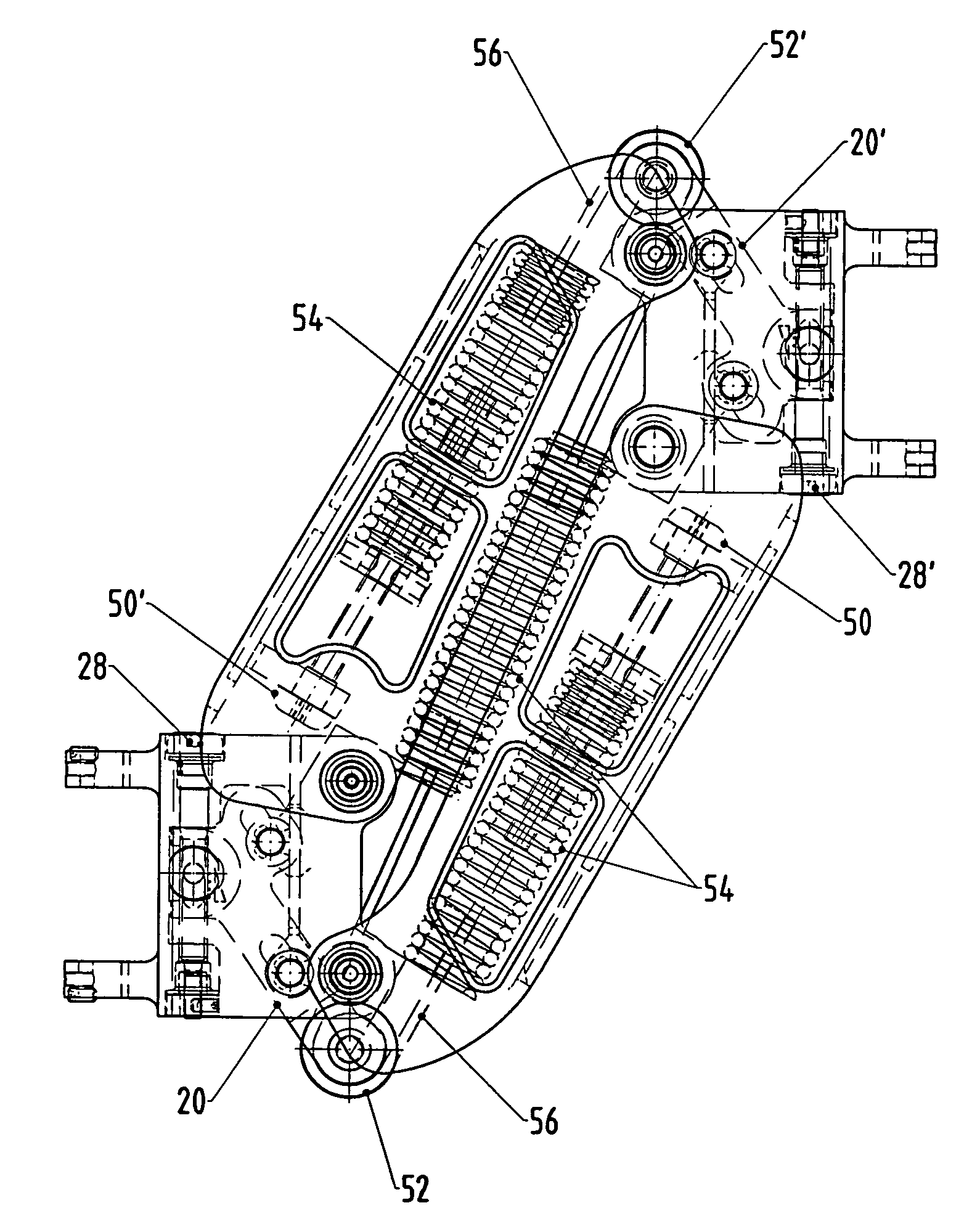
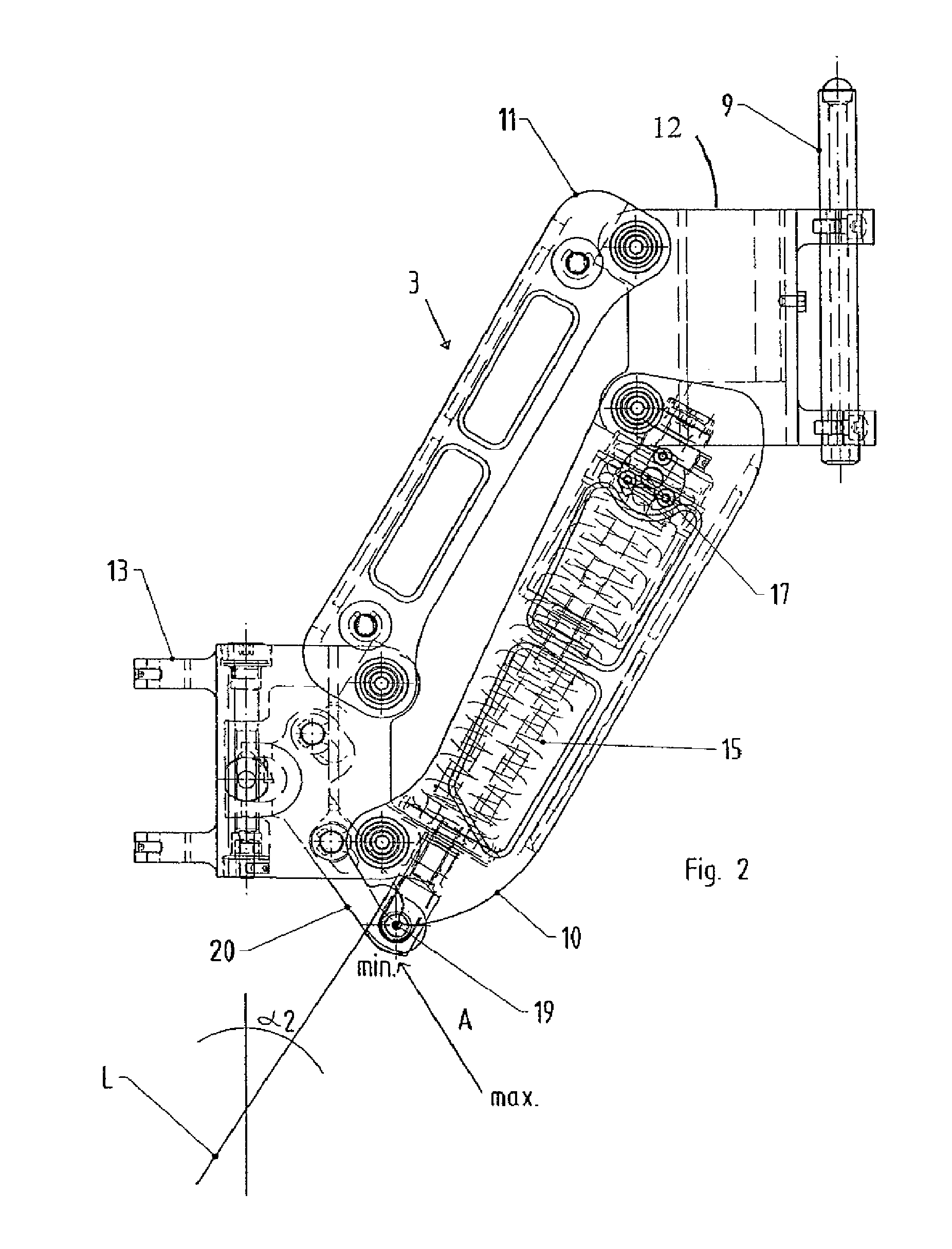
[0035]The two parallelogram guides 3 and 5 are basically identical in design. Therefore, only parallelogram 3 is represented in FIGS. 2 to 5; however, all the explanations of it also apply equally to parallelogram guide 5.

[0036]Parallelogram guide 3 is formed by two opposing legs 10, 11 disposed parallel to one another and two connecting elements 12, 13, whic...


PUM


Abstract

A spring arm (1) for a camera body support is provided with a parallelogram guide (3, 5) which is made up of two opposing legs (10, 11) disposed parallel to one another and two likewise opposing connecting elements (12, 13) that connect the respective ends of the legs (10, 11) with one another, and an energy storage mechanism (15), which is supported on two pivot points (17, 19) on the parallelogram guide (3, 5), in order to compensate a load acting on the parallelogram guide (3, 5). At least one (19) of these pivot points (17, 19) is adjustable in relation to the parallelogram guide (3, 5) such that both the energy storage mechanism's (15) pretension and also its action of force direction change.

Description

TECHNICAL FIELD[0001]The present invention relates to a body support having a spring arm according to the preamble of claim 1.PRIOR ART[0002]Body supports for cameras with a spring arm have inherently been known since the mid 70s and have been described for example in U.S. Pat. Nos. 4,017,168, 4,156,512, 4,208,028 and 4,394,075 as well as U.S. Pat. No. 6,030,130. The spring arm of the body support is fixed on one of its ends to the cameraman's body by way of a carrying strap, and the camera is attached on the other end of the spring arm either simply by way of a camera sled or also by way of a pendulum system (gimbal). The camera's weight is supported on the cameraman's body by means of the body support. This makes guiding the camera considerably easier by comparison with a situation where the cameraman has to hold the whole weight of the camera in his hands.[0003]In this regard the camera's movement is essentially decoupled from the cameraman's movement. Thus the cameraman can shoo...

Claims


Application Information

Patent Timeline
Patent Type & Authority Patents(United States)
IPC IPC(8): A47F5/00
CPCF16M11/04F16M11/2014F16M11/2092F16M13/04F16M11/24F16M2200/063F16M2200/044
Inventor HEIN, DIETERSCHALLER, CURT O.SEIPEL, ROLAND
Owner CAMERA DYNAMICS
Why Eureka
Try Eureka