Wireless Power Transmission System, Transmitter, and Receiver

a power transmission system and wireless technology, applied in the field of wireless power transmission systems, transmitters and receivers, can solve the problems of inability to say, stop transmitting power, abnormality, etc., and achieve the effect of improving average transmission efficiency, average power transmission efficiency, and improving average transmission efficiency

Inactive Publication Date: 2012-06-14
HITACHI LTD
View PDF13 Cites 278 Cited by
  • Summary
  • Abstract
  • Description
  • Claims
  • Application Information

AI Technical Summary

Benefits of technology

[0011]An advantage of the present invention is to provide a wireless power transmission system, a transmitter, and a receiver that realize averagely efficient power transmission even if the apparatuses are in a normal state but the transmission efficiency varies from moment to moment.
[0012]Another advantage of the present invention is provide a wireless power transmission system, a transmitter, and a receiver that can properly transmit power to the receiver even when the environment varies, reduce situations where the receiver must stop operating, and improve average transmission efficiency.
[0013]A wireless power transmission system according to an aspect of the present invention includes: a receiver; and a transmitter that wirelessly transmits power to the receiver. The transmitter includes: a power transmission unit that transmits power; and a power adjustment unit that adjusts power to be transmitted by the transmitter. The receiver includes: a power receiving unit that receives the power from the transmitter; and a power storage u

Problems solved by technology

When the transmission efficiency falls below a predetermined value, it determines that an abnormality has occurred and can stop transmitting power.
However, it cannot be said that the transmission efficiency is always the same value unless

Method used


Image

  • Wireless Power Transmission System, Transmitter, and Receiver
  • Wireless Power Transmission System, Transmitter, and Receiver
  • Wireless Power Transmission System, Transmitter, and Receiver

Examples


first embodiment

[0041]In this embodiment, an example of a wireless power transmission system that adjusts power to be transmitted by a transmitter on the basis of power transmission efficiency and the amount of power stored in a receiver will be described with reference to FIGS. 1 to 4C.

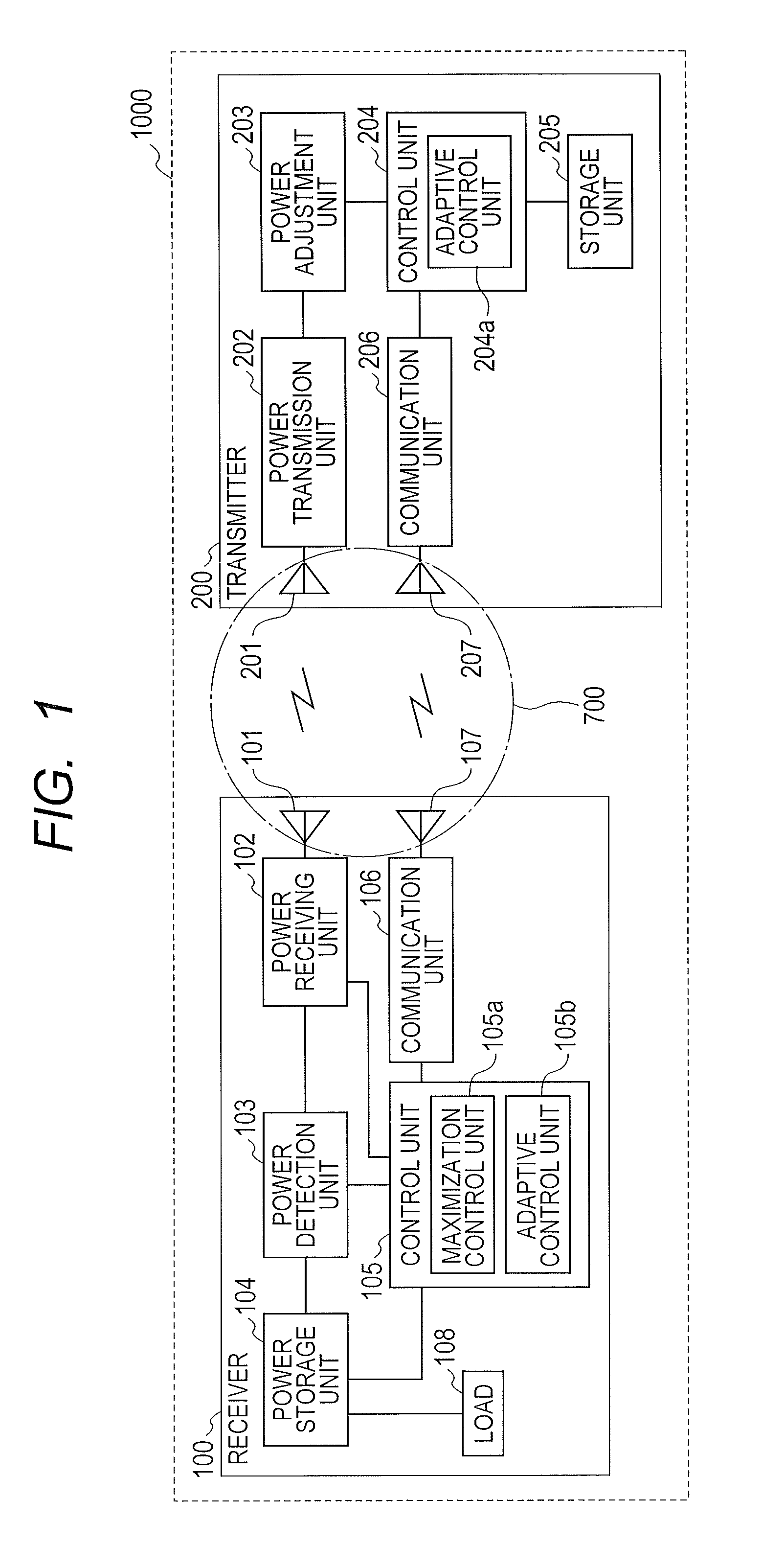
[0042]FIG. 1 is an example configuration of the wireless power transmission system according to this embodiment. A wireless power transmission system 1000 includes a receiver 100 and a transmitter 200. The receiver 100 includes a power receiving antenna 101, a power receiving unit 102, a power detection unit 103, a power storage unit 104, a control unit 105, a communication unit 106, and a communication antenna 107. An electronic apparatus such as a cellular phone is coupled to the power storage unit 104 as a load 108.

[0043]The transmitter 200 includes a power transmission antenna 201, a power transmission, unit 202, a power adjustment unit 203, a control unit 204, a storage unit 205, a communication unit 206, and a...

second embodiment

[0067]A wireless power transmission system, a transmitter, and a receiver according to a second embodiment of the present invention will be described with reference to FIGS. 5 to 6B. In this embodiment, the power to be transmitted by the transmitter is adjusted on the basis of the present power transmission efficiency and the past power transmission efficiency with respect to a certain receiver and the amount of power stored in the receiver. In this embodiment, the transmission efficiency is calculated on the basis of the present and the past (one to multiple cycles) power transmission efficiency histories, in other words, on the basis of the cumulative incidence.

[0068]FIG. 5 is a flowchart a process performed by the transmitter and the receiver according to this embodiment. The configuration and flow related to the received power maximization are the same as those in the first embodiment and will not be described. (The same goes for the other embodiments.)

[0069]The transmitter 200 ...

third embodiment

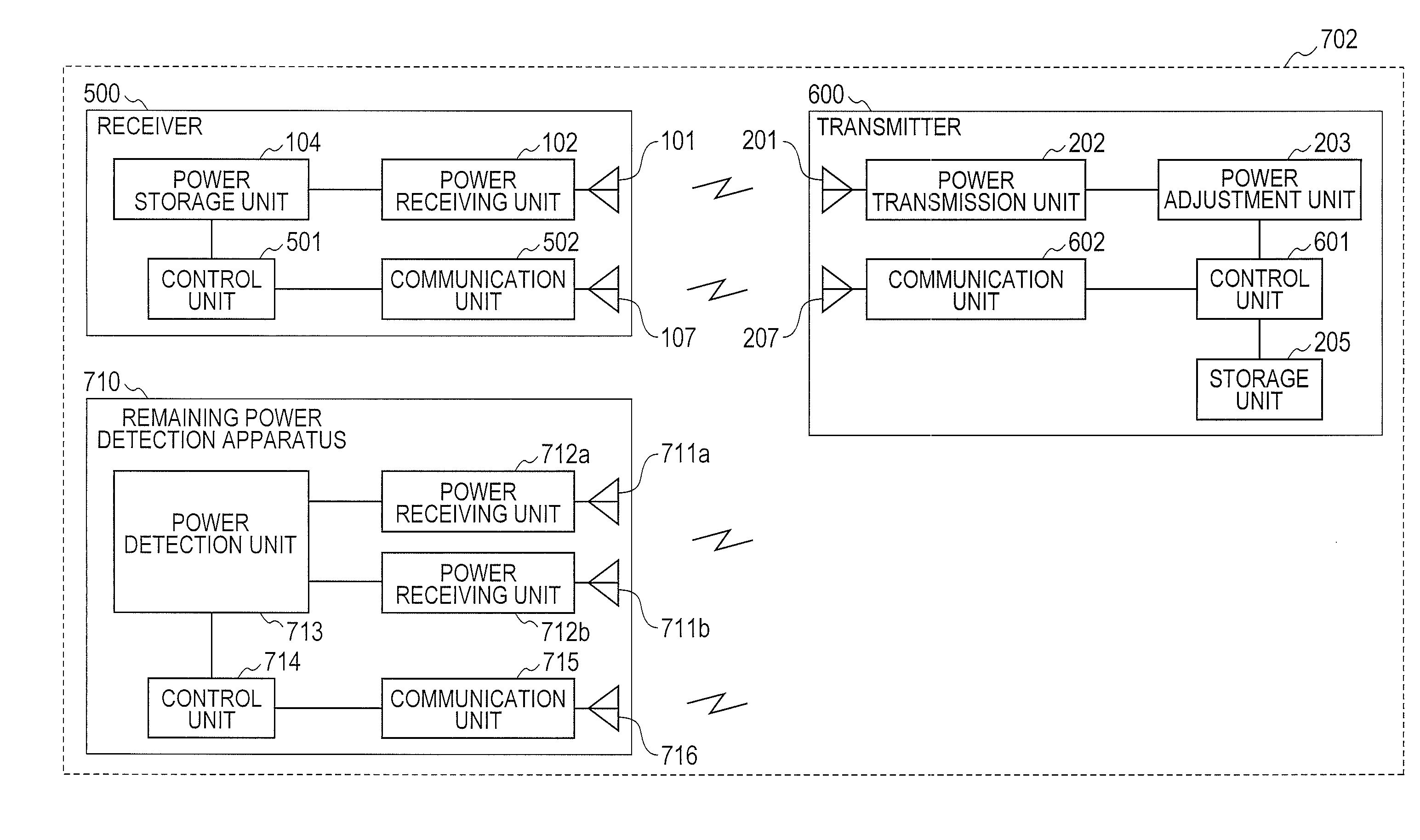
[0078]A wireless power transmission system, a transmitter, and a receiver according to a third embodiment will be described with reference to FIGS. 7 to 8. In this embodiment, the transmitter adjusts power to be transmitted thereby on the basis of the power transmission efficiency, the amount of power stored in the receiver, and the power consumption of the receiver.

[0079]FIG. 7 is a flowchart a process performed by the transmitter and the receiver according to this embodiment.

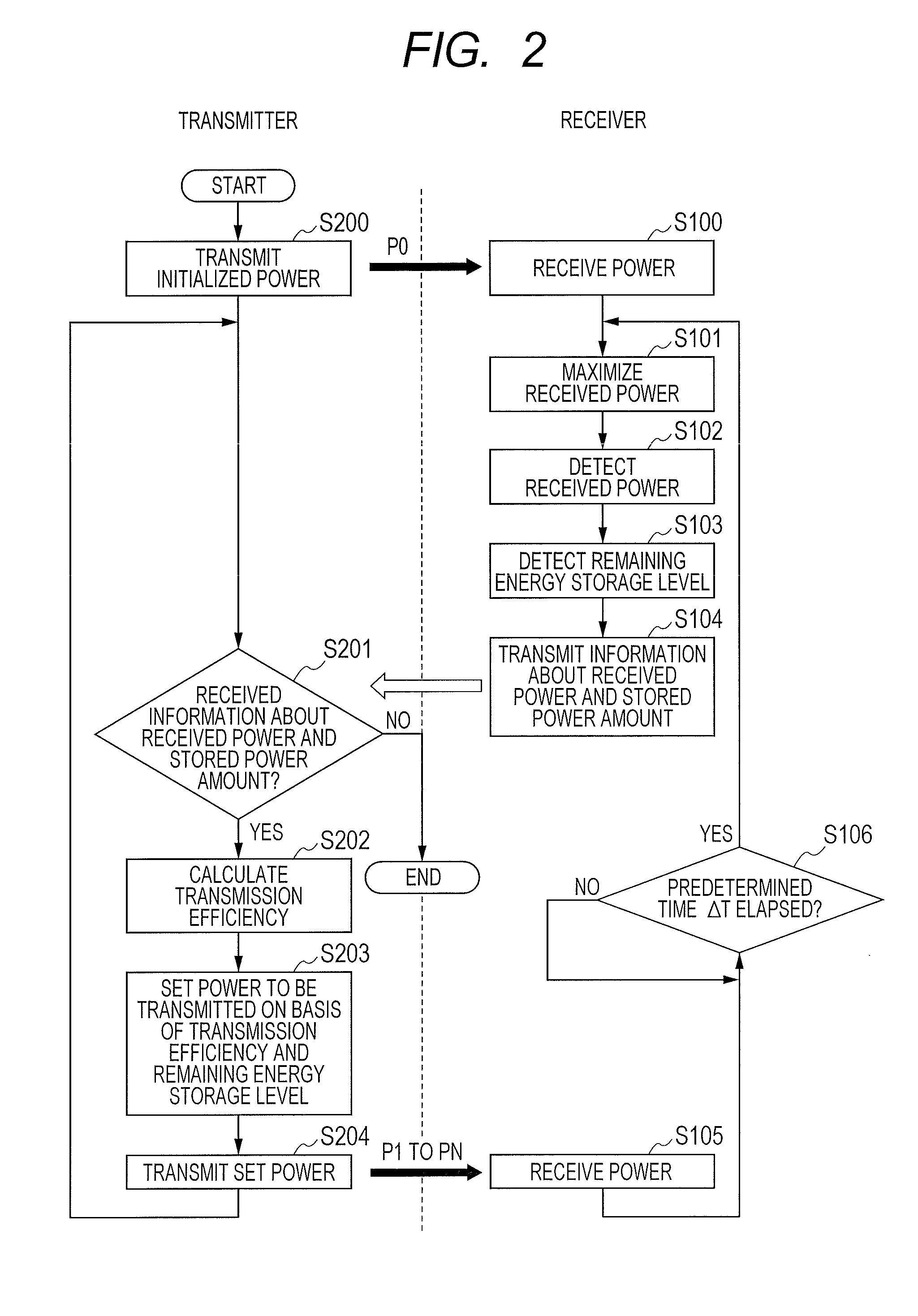
[0080]The transmitter 200 initializes the power adjustment unit 203 and transmits initialized power from the power transmission unit 202 (S200). The receiver 100 receives the initialized power 5200 at the power receiving unit 102 (S100). The control unit 105 then controls the power receiving unit 102 so that the received power is maximized (S101). The power detection unit 103 then detects the received power (S102). The control unit 105 then detects the amount of power stored in the power storage unit 104 (S103...


PUM


Abstract

A wireless power transmission system includes a receiver and a transmitter. The transmitter includes: a power transmission unit that transmits power; a power adjustment unit that adjusts power to be transmitted; and a communication unit. The receiver includes: a power receiving unit that receives power; a power detection unit that detects the received power; a power storage unit that stores the received power; and a communication unit. The power to be transmitted is adjusted on the basis of power transmission efficiency and the remaining energy storage level. The power transmission efficiency is the ratio between the transmitted power and the received power.

Description

CLAIM OF PRIORITY[0001]The present application claims priority from Japanese patent application JP 2010-276099 filed on Dec. 10, 2010, the content of which is hereby incorporated by reference into this application.FIELD OF THE INVENTION[0002]The present invention relates to a wireless power transmission system, a transmitter, and a receiver. In particular, the invention relates to a wireless power transmission system, a transmitter, and a receiver that are suitable for apparatuses which may be used in an environment where the distance from a power supply unit varies, such as portable terminal devices.BACKGROUND OF THE INVENTION[0003]Wireless power transmission systems have been developed that wirelessly transmit power using electromagnetic induction, magnetic coupling, or the like. Examples of such a wireless power transmission system include systems for charging portable terminal devices.[0004]Japanese Unexamined Patent Publication No. 2010-51137 discloses a transmitter and a recei...

Claims


Application Information

Patent Timeline
IPC IPC(8): H04W52/04H01F38/14H02J7/00
CPCH02J7/025Y02B60/50H04B5/0037H02J50/05H02J50/10H02J50/80H02J7/00034H02J50/12
Inventor TERADA, TAKAHIDESHINODA, HIROSHIYAMAMOTO, KEISUKE
Owner HITACHI LTD
Why Eureka
Try Eureka