Motion prediction for wireless power transfer

a wireless power transfer and motion prediction technology, applied in mechanical vibration separation, instruments, transportation and packaging, etc., can solve the problems of restricting the movement of the device, limiting its operation, inconvenient and restrictive,

Active Publication Date: 2015-11-19
UBEAM
View PDF0 Cites 287 Cited by
  • Summary
  • Abstract
  • Description
  • Claims
  • Application Information

AI Technical Summary

Problems solved by technology

This can restrict the movement of the device and limit its operation to within a certain maximum distance from the power source.
Even

Method used


Image

  • Motion prediction for wireless power transfer
  • Motion prediction for wireless power transfer
  • Motion prediction for wireless power transfer

Examples


Embodiment Construction

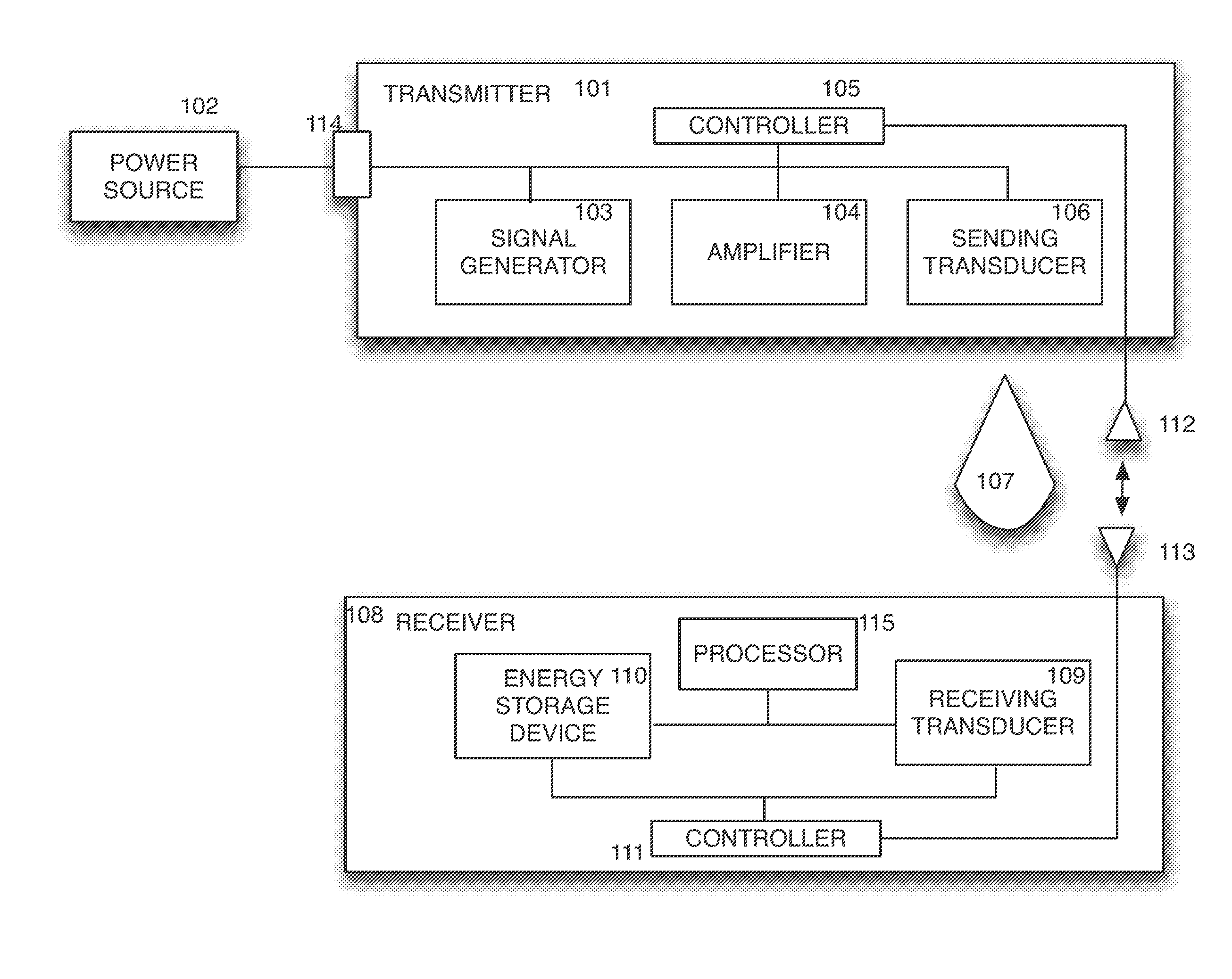
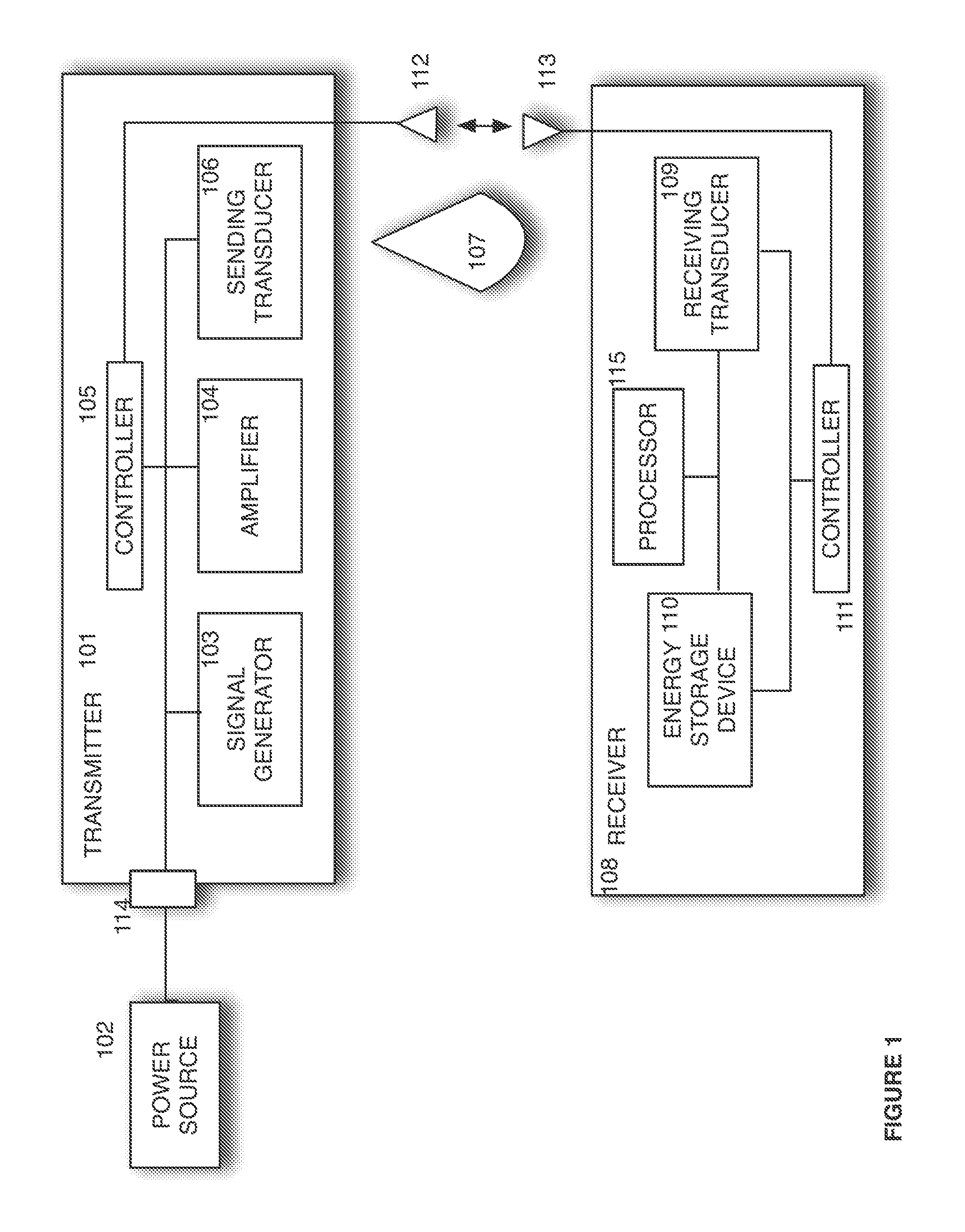
[0010]Embodiments of the disclosed subject matter can convert electrical energy into acoustic energy, which can be beamed to a device where it is converted back into electrical energy. The converted electrical energy can be used to power the device and to charge one or more energy storage components of the device, such as a battery, a capacitor, etc. This can obviate the need for constant or periodic tethering to a power source using a cord. Embodiments can transfer energy to several devices at once, in rotation or in any suitable sequence, with dwell times of any suitable duration.

[0011]FIG. 1 shows a system in accordance with the disclosed subject matter. Transmitter 101 can receive electrical energy from power source 102 (such as an electrical outlet or a battery) as input. Signal generator 103 can generate a signal that can be amplified by amplifier 104. This can be done under the control of controller 105. The amplified signal can be sent to sending transducer 106, and the ultr...


PUM


Abstract

A signal generator generates an electrical signal that is sent to an amplifier, which increases the power of the signal using power from a power source. The amplified signal is fed to a sender transducer to generate ultrasonic waves that can be focused and sent to a receiver. The receiver transducer converts the ultrasonic waves back into electrical energy and stores it in an energy storage device, such as a battery, or uses the electrical energy to power a device. In this way, a device can be remotely charged or powered without having to be tethered to an electrical outlet.

Description

CROSS-REFERENCE TO RELATED APPLICATIONS[0001]This application claims the benefit as a continuation-in-part of U.S. patent application Ser. No. 14 / 635,861, filed on Mar. 2, 2015, which claims the benefit of U.S. patent application Ser. No. 13 / 477,551, filed on May 22, 2012, which claims the benefit of U.S. Provisional Patent Application No. 61 / 490,988, filed May 27, 2011, all of which are herein incorporated herein by reference in their entirety. This application is also related to U.S. patent application Ser. No. 13 / 477,542, entitled, “Sender Communications for Wireless Power Transfer”; U.S. patent application Ser. No. 13 / 477,551, entitled “Receiver Communications for Wireless Power Transfer”; U.S. patent application Ser. No. 13 / 477,555, entitled “Sender Transducer for Wireless Power Transfer”; U.S. patent application Ser. No. 13 / 477,557, entitled, “Receiver Transducer for Wireless Power Transfer”; U.S. patent application Ser. No. 13 / 477,565, entitled, “Sender Controller for Wireles...

Claims


Application Information

Patent Timeline
IPC IPC(8): H04B5/00H02J7/02H02J7/04H02J5/00
CPCH04B5/0037H02J7/04H02J7/025H02J5/005G10K11/346H04B11/00G10K11/348B06B1/0207B06B2201/51H02J50/80H02J50/15H02J7/00034H02J50/90
Inventor PERRY, MEREDITHREYNOLDS, PAULTAFFLER, SEANJOYCE, ANDREW
Owner UBEAM
Why Eureka
Try Eureka