Synchronous spacer with a guiding block

a technology of guiding block and spacer, which is applied in the direction of bearings, shafts and bearings, bearings, etc., can solve the problems of serious affecting the operation the inability to move the rolling elements, and the serious affecting of the linear guideway, so as to reduce the impact distance and effectively reduce the noise and impact

Active Publication Date: 2009-07-21
HIWIN TECH
View PDF12 Cites 5 Cited by
  • Summary
  • Abstract
  • Description
  • Claims
  • Application Information

AI Technical Summary

Benefits of technology

[0017]The primary objective of the present invention is to provide a synchronous spacer with a guiding block, which prevents the occurrence of interference while improving the stability of the linear guideway.
[0018]To achieve the abovementioned objective, the synchronous spacer with a guiding block comprises strip-shaped links and a guiding block fixed at the end thereof. The guiding block is formed with an arc-shaped surface for cooperating with the inner surface of the track of the linear guideway. With the guidance of the guiding block, the synchronous spacer is prevented from impacting the inner surface of the track, enabling the linear guideway to move smoothly and stably.
[0020]An arch-shaped surface is formed on the guiding block and is located correspondingly to inner surface of the track of the linear guideway, the guiding block is larger than spacer element of the synchronous spacer but is smaller than the rolling elements. The guiding block reduces the impact distance and forces the synchronous spacer to move along the predetermined route, thus effectively reducing the noise and the impact caused when the rolling elements circulate along the track.

Problems solved by technology

Firstly, when the synchronous spacer 10 moves from the circulating groove A of the loading area to the return portion B, since there are two spacer elements 11 and the link 12 at both ends of the synchronous spacer 10, plus each of the spacer elements 11 has two angular edges formed at both sides thereof, the spacer elements 11 will move linearly into the return portion B, impacting the inner surface B1 thereof, and then move along the inner surface B1 of the return portion (as shown in FIG. 1). Further, the spacer elements 11 and the link 12 at both ends of the synchronous spacer 10 will impact the connecting portion D (the assembly clearance) between the return portion B and the circulating groove A. Therefore, the synchronous spacer 10 cannot move smoothly into the return portion B.
Secondly, when the synchronous spacer 10 moves from the return portion B to the circulating groove A of the loading area, since there are two spacer elements 11 and the link 12 at both ends of the synchronous spacer 10, plus each of the spacer elements 11 has two angular edges, the spacer elements 11 will move into the circulating groove A in the tangent direction thereof, impacting the inner surface C of the circulating groove A, and then move linearly along the inner surface C (as shown in FIG. 2). Therefore, the synchronous spacer 10 cannot move smoothly into the return portion B, causing unstable motion of the rolling elements 13.
Thirdly, when the spacer 10 circulates within the linear guideway, the rolling elements 13 cannot move along the predetermined path due to the influence of impact and interference, and the rolling elements 13 will be subjected to many times of impact during movement, thereby seriously affecting the operation of the linear guideway.
The rolling elements 13 will deviate from the predetermined path and will be subjected to many times of impact during movement, thereby seriously affecting the operation of the linear guideway, and even causing noise.

Method used


Image

  • Synchronous spacer with a guiding block
  • Synchronous spacer with a guiding block
  • Synchronous spacer with a guiding block

Examples


Embodiment Construction

[0037]The present invention will be more clear from the following description when viewed together with the accompanying drawings, which show, for purpose of illustrations only, the preferred embodiment in accordance with the present invention.

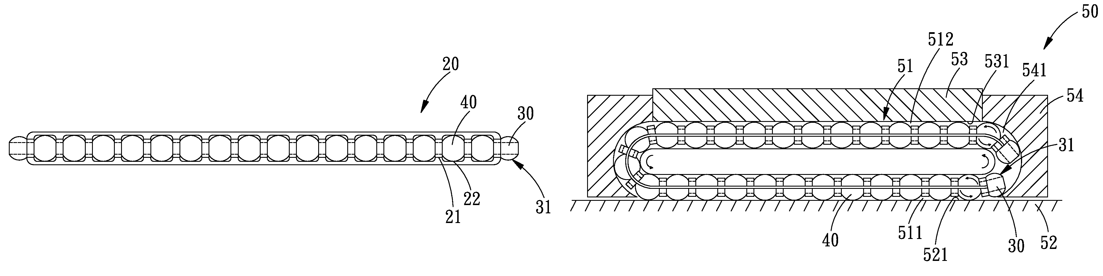
[0038]Referring to FIGS. 5-8, a synchronous spacer 20 with guiding blocks in accordance with the present invention at least comprises: a plurality of spacer elements 21, two strip-shaped links 22, and two guiding blocks 30. A plurality of rolling elements 40 is formed in the rack 51 of a linear guideway 50. The linear guideway 50 includes a rail 52, a sliding block 53 and two end caps 54 (linear guideway 50 is of a conventional design, so further explanation is omitted).

[0039]The synchronous spacer 20 is strip-shaped and includes a plurality of spacer elements 21 and two strip-shaped links 22 disposed at both sides of the plurality of spacer elements 21. The spacer elements 21 are maintained between the rolling elements 40. The synchronous spa...


PUM


Abstract

A synchronous spacer with a guiding block comprises strip-shaped links, a plurality of spacer elements, and a guiding block fixed at the end of the links. An arch-shaped surface is formed on the guiding block and is located correspondingly to inner surface of the track of the linear guideway, the guiding block is larger than spacer element of the synchronous spacer but is smaller than the rolling elements. With the guidance of the guiding block, the synchronous spacer is prevented from impacting the inner surface of the track, enabling the linear guideway to move smoothly and stably.

Description

BACKGROUND OF THE INVENTION[0001]1. Field of the Invention[0002]The present invention relates to a spacer for a linear guideway, and more particularly to a synchronous spacer with a guiding block, which prevents the occurrence of interference while improving the stability of the linear guideway.[0003]2. Description of the Prior Art[0004]Linear guideway is used more and more widely in modern industries. In addition to its high precision transmission performance, the linear guideway also has many other advantages, such as low friction loss, high ratio of energy conversion, low noise, high rigidity and wear-resistance. Therefore, it is self-evident that the linear guideway is very important to various industrial mechanisms. Normally, various linear guideways are provided with sliding bock, rail, and rolling elements that are used for linear and rotary application. However, to obtain the following objectives:[0005]1, preventing the rolling elements from falling off the sliding block whe...

Claims


Application Information

Patent Timeline
Patent Type & Authority Patents(United States)
IPC IPC(8): F16C29/06F16C19/00
CPCF16C33/3825F16C29/06
Inventor LIAO, CHI-MENGLIN, YUN-YI
Owner HIWIN TECH
Why Eureka
Try Eureka