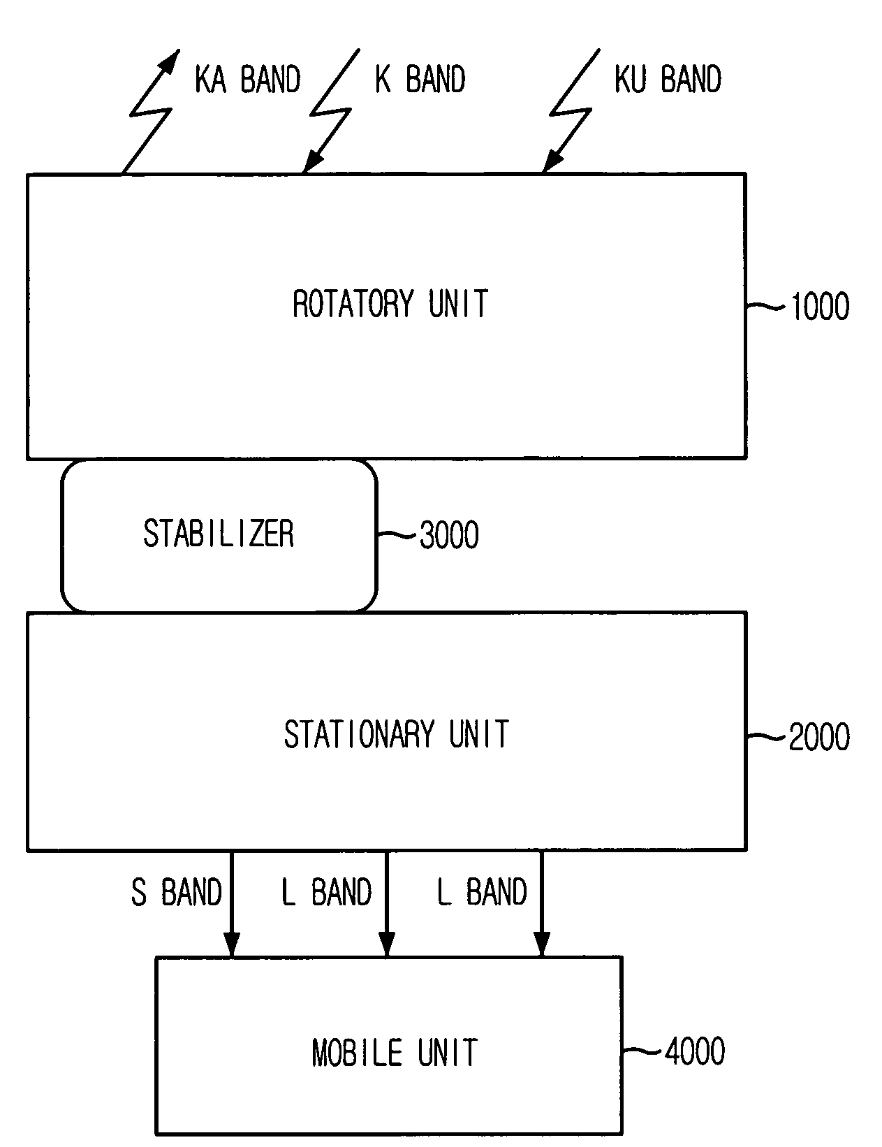
Hybrid antenna system
a hybrid antenna and antenna technology, applied in the direction of antennas, electrically long antennas, antennas, etc., can solve the problems of high gain characteristics, expensive implementation costs, and almost impossible to use the conventional mechanical antenna system to track a satelli
- Summary
- Abstract
- Description
- Claims
- Application Information
AI Technical Summary
Benefits of technology
Problems solved by technology
Method used
Image

Examples
first embodiment
[0065]As shown in the top view (a) of FIG. 5, the radiating unit includes a main reflector 1111-a, a sub reflector 1112-a and an active feed array 1113-a, which are arranged in a limited circle.
[0066]Also, edges of the sub reflector 1112-a and the active feed array 1113-a have a modified oval shape and the surface of the sub reflector 1112-a is a flat plate shape.
[0067]The side view (b) of the sub reflector 1112-a in FIG. 5 clearly shows the flat plate shape surface.
second embodiment
[0068]FIG. 6 is a top view and a side view of radiating unit 1100 in accordance with the present invention.
[0069]As shown in the top view (a) of FIG. 6, the radiating unit 1100 according to the second embodiment includes a main reflector 1111-b, a sub reflector 1112-b and an active feed array 1113-b.
[0070]Edges of the sub reflector 11120-b and the active feed array 1113-b have a circular shape and a surface of the sub reflector 1112-b is properly shaped.
[0071]The side view (b) of the sub reflector 1112-b in FIG. 6 clearly shows the shaped surface.
[0072]In the radiating unit 1110 according to the first and the second embodiments, if the radiating units 1110 of the first and the second embodiments have the same aperture shape of the main reflectors, similar size of sub reflectors and the same number of feed arrays, the radiating units 1110 of the first and the second embodiments provide very similar electric characteristics. Hence, the present invention will be described based on the...
PUM
 Abstract
Description
Claims
Application Information
 - R&D Engineer
- R&D Manager
- IP Professional
- Industry Leading Data Capabilities
- Powerful AI technology
- Patent DNA Extraction
Browse by: Latest US Patents, China's latest patents, Technical Efficacy Thesaurus, Application Domain, Technology Topic.
© 2024 PatSnap. All rights reserved.Legal|Privacy policy|Modern Slavery Act Transparency Statement|Sitemap