Drive unit

a technology of drive unit and piezoelectric element, which is applied in the direction of piezoelectric/electrostrictive/magnetostrictive devices, piezoelectric/electrostriction/magnetostriction machines, electrical apparatus, etc., can solve the problems of significant deterioration in the performance of optical systems, movable object tilting, and difficult to accurately carry out positional control of drive units that use such piezoelectric elements. , to achieve th

Inactive Publication Date: 2009-07-28
KONICA MINOLTA OPTO
View PDF7 Cites 316 Cited by
  • Summary
  • Abstract
  • Description
  • Claims
  • Application Information

AI Technical Summary

Benefits of technology

[0036]With the present invention, in the case that the movable object is stopped at the position where the movable object is made contact with the restricting member, the tilting of the movable object owing to the contact of the movable object with the restricting member can be corrected. In other words, the tilting of the movable object, caused when the movable object makes contact with the restricting member, can be corrected by vibrating the supporting member so that the movable object is not moved substantially after the movable object is made contact with the restricting member. Hence, the movable object can be positioned without using a sensor or the like. Furthermore, the displacement of the optical axis due to the displacement of the optical member provided in the movable object can be prevented.
[0037]In addition, the movable object can be brought to a state in which the movable object is not moved while the vibration of the electromechanical transducer is obtained securely, by applying a rectangular drive signal having a duty ratio of 0.5 as the second wave drive signal. Hence, the tilting of the movable object can be corrected, without changing the position of the movable object.
[0039]Still further, because the position of the movable object being in contact with the restricting member can be detected accurately, the positional detection of the movable object can be carried out easily using the position of the movable object as a reference position.

Problems solved by technology

However, it is difficult to accurately carry out positional control for the drive unit that uses such a piezoelectric element.
However, in the case that the movable object is made contact with the restricting member (the supporting section 3) and stopped, if the driving of the piezoelectric element is not stopped immediately after the movable object is made contact with the restricting member, there is a problem in which the movable object is tilted as shown in FIG. 4B.
Although the tilting of the movable object is very slight, in the case of the drive unit connected to an optical member, such as a lens 12, the tilting becomes a cause of significant deterioration in the performance of the optical system.
However, such a configuration in which the restricting member is made larger and a sensor is provided is not desirable from the viewpoint of downsizing the optical system, such as a lens barrel, in recent years.
Furthermore, providing a sensor causes a problem of increasing cost.

Method used


Image

  • Drive unit
  • Drive unit
  • Drive unit

Examples


Embodiment Construction

[0055]Before the description of the present invention proceeds, it is to be noted that like parts are designated by like reference numerals throughout the accompanying drawings. A drive unit according to an embodiment of the present invention will be described below referring to the drawings.

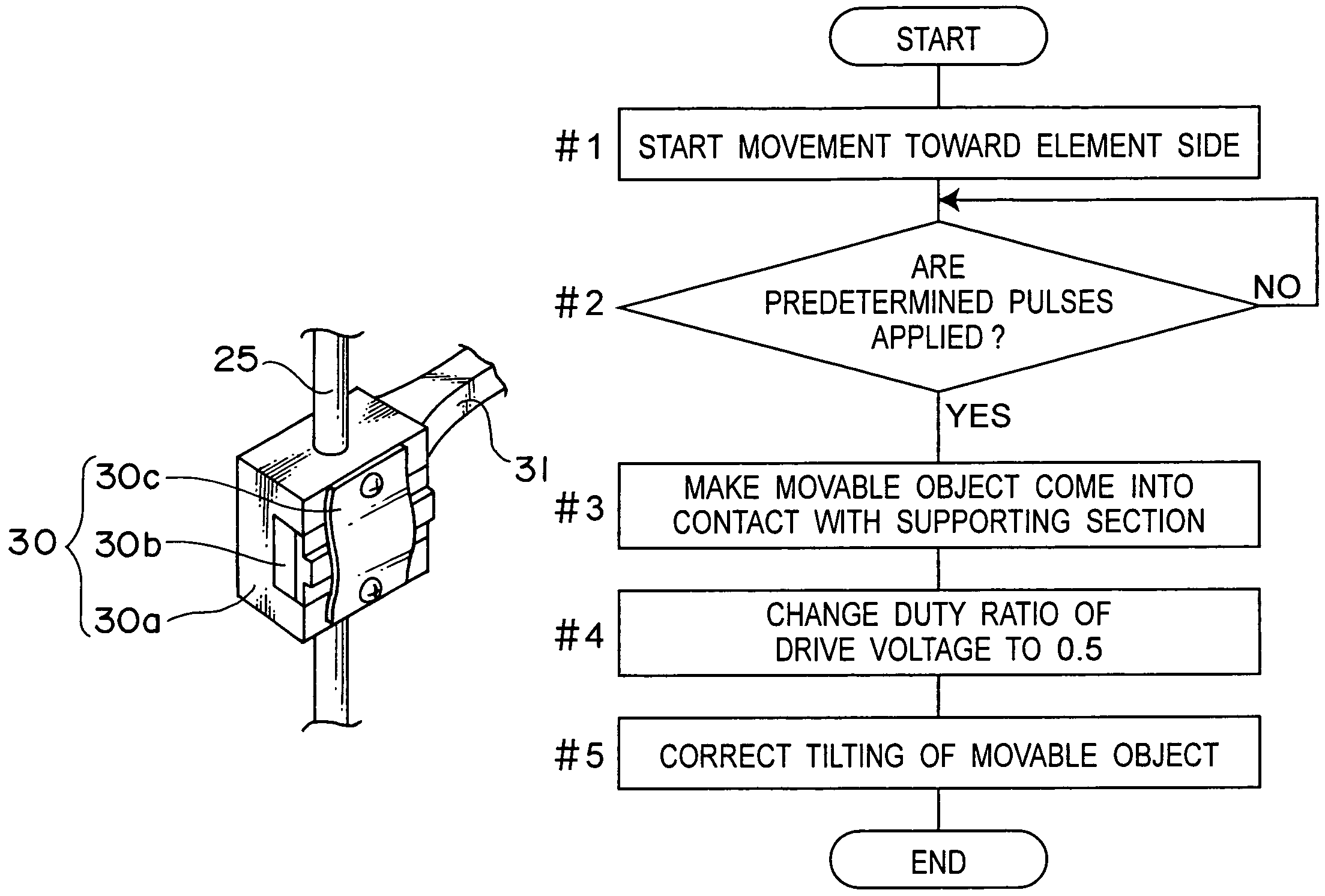
[0056]FIG. 5A is a schematic view showing a configuration of a drive unit according to this embodiment of the present invention. The drive unit 20 according to this embodiment is used to drive a lens frame 31 in which an optical lens 32 being used in a lens barrel of a camera is provided.

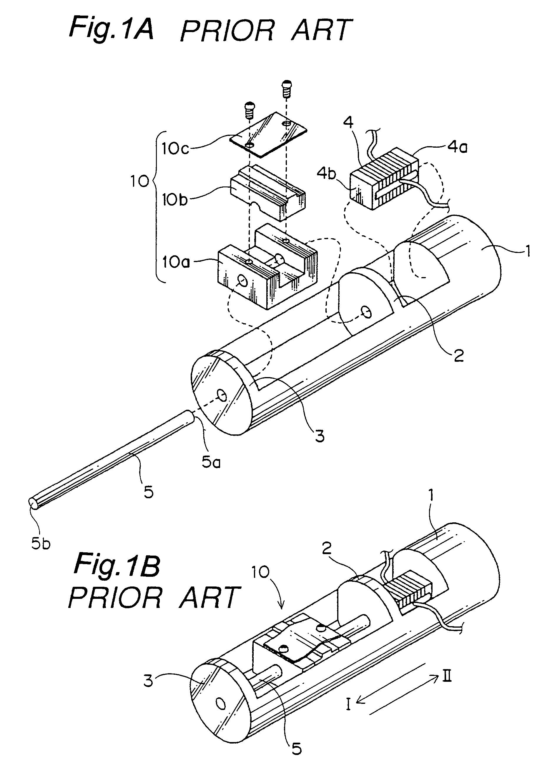
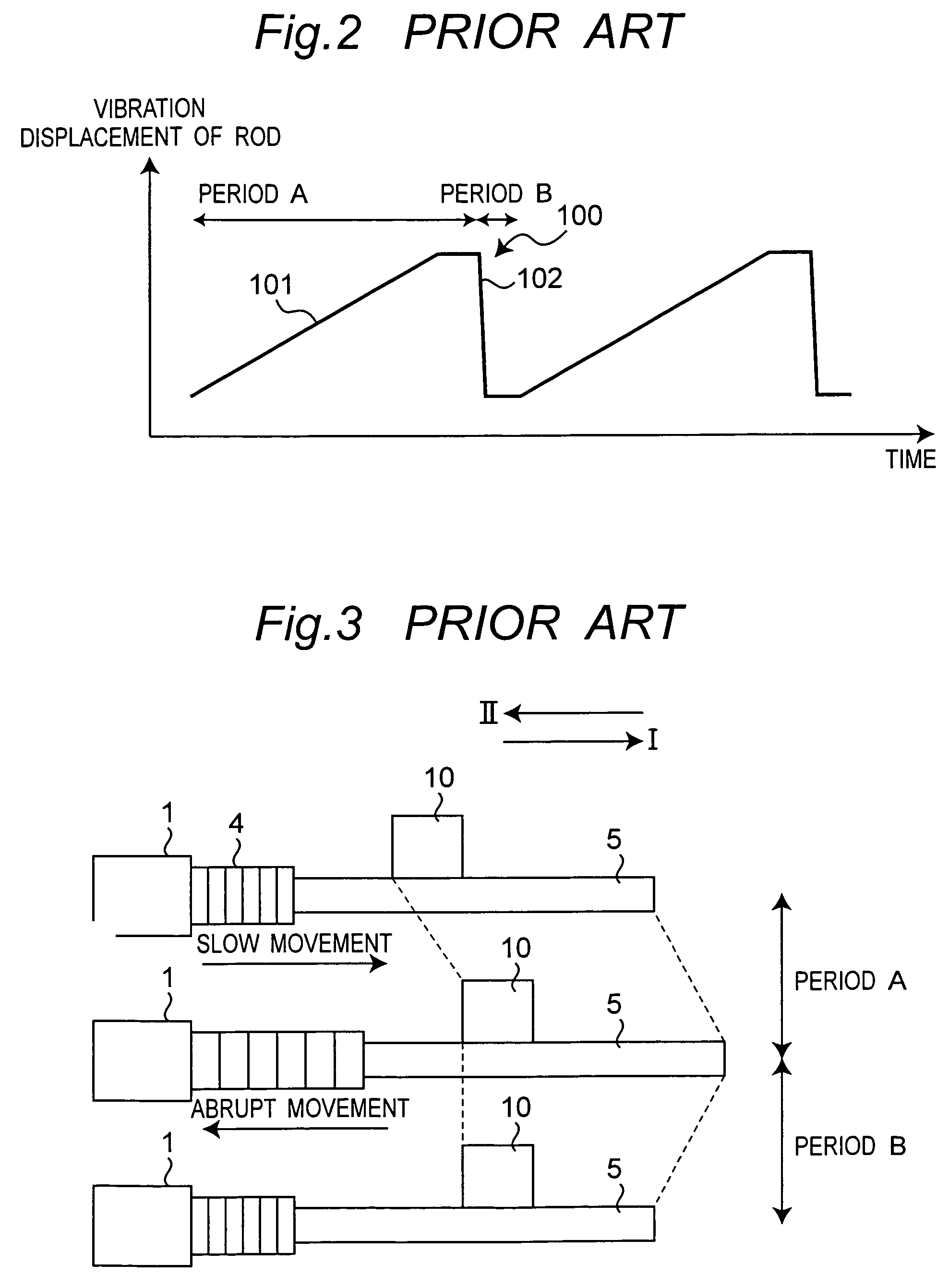
[0057]The drive unit 20 drives a movable object 30 on the basis of the same principle as that of the drive unit that uses a piezoelectric element 4 shown in FIG. 1. The piezoelectric element 24 of the drive unit 20 comprises multiple piezoelectric plates stacked. One end thereof in an expansion / contraction direction is secured to a frame 21, and the other end thereof is secured to an end of a rod 25. The rod 25 ...


PUM


Abstract

A drive unit being characterized in that a movable object can be prevented from being tilted when the movable object is stopped using a restricting member. The drive unit comprises a piezoelectric element, a rod provided at an end of the piezoelectric element, a movable object frictionally engaged with the rod, and drive pulse generating means that apply drive signals to the piezoelectric element. The drive pulse generating means apply to the piezoelectric element a rectangular wave drive signal that has a duty ratio other than 0.5 and vibrates the rod so that a difference occurs between the expansion and contraction of the rod when the movable object is moved, and apply to the piezoelectric element a rectangular wave drive signal that has a duty ratio of 0.5 and vibrates the rod so that the movable object is not moved substantially when it is detected that the movable object is in contact with a restricting member.

Description

BACKGROUND OF THE INVENTION[0001]The present invention relates to a drive unit for driving a movable object incorporating mainly an optical component, such as a lens being used in a camera, a DVD drive, a CD drive, an MD drive, an endoscope or the like.[0002]As a drive unit that uses an electromechanical transducer, such as a piezoelectric element, which changes its dimension (expands or contracts) when a voltage is applied, the drive unit shown in an exploded perspective view in FIG. 1A and in an assembled perspective view in FIG. 1B, for example, is known (U.S. Pat. No. 6,016,231).[0003]A piezoelectric element 4 comprises multiple piezoelectric plates stacked. One end 4a thereof in the expansion / contraction direction is secured to a base 1, and the other end 4b thereof is secured to the first end 5a of a rod (supporting member) 5. The rod 5 is slidably supported on supporting sections 2 and 3 integrated with the base 1.[0004]The rod 5 is held between the main unit 10a and the cap ...

Claims


Application Information

Patent Timeline
Patent Type & Authority Patents(United States)
IPC IPC(8): H01L41/08H02N2/00
CPCH02N2/067H02N2/025
Inventor NAMIKAWA, TAKETO
Owner KONICA MINOLTA OPTO
Why Eureka
Try Eureka