Sample tube holder

Inactive Publication Date: 2009-08-04
LEIDOS
View PDF147 Cites 5 Cited by
  • Summary
  • Abstract
  • Description
  • Claims
  • Application Information

AI Technical Summary

Problems solved by technology

If the seal between the sample tube and the manifold is not secure and leakage occurs, then the sample results are compromised and cannot be trusted.
Forming a secure seal on the end of a sample tube is difficult because an end seal requires that the tube end meet strict requirements for flatness and squareness.
A chip or other imperfection on the tube end creates a potential leakage site causing an end seal to fail.
It is also possible to use an O-ring to form a seal on the outside diameter of the tube, but that type of seal often makes it difficult to insert the tube end into and to remove it from a mating fitting on the vacuum manifold.
Another complication arises from the fact that variation in the length of sample tubes is common.

Method used


Image

  • Sample tube holder
  • Sample tube holder

Examples


Embodiment Construction

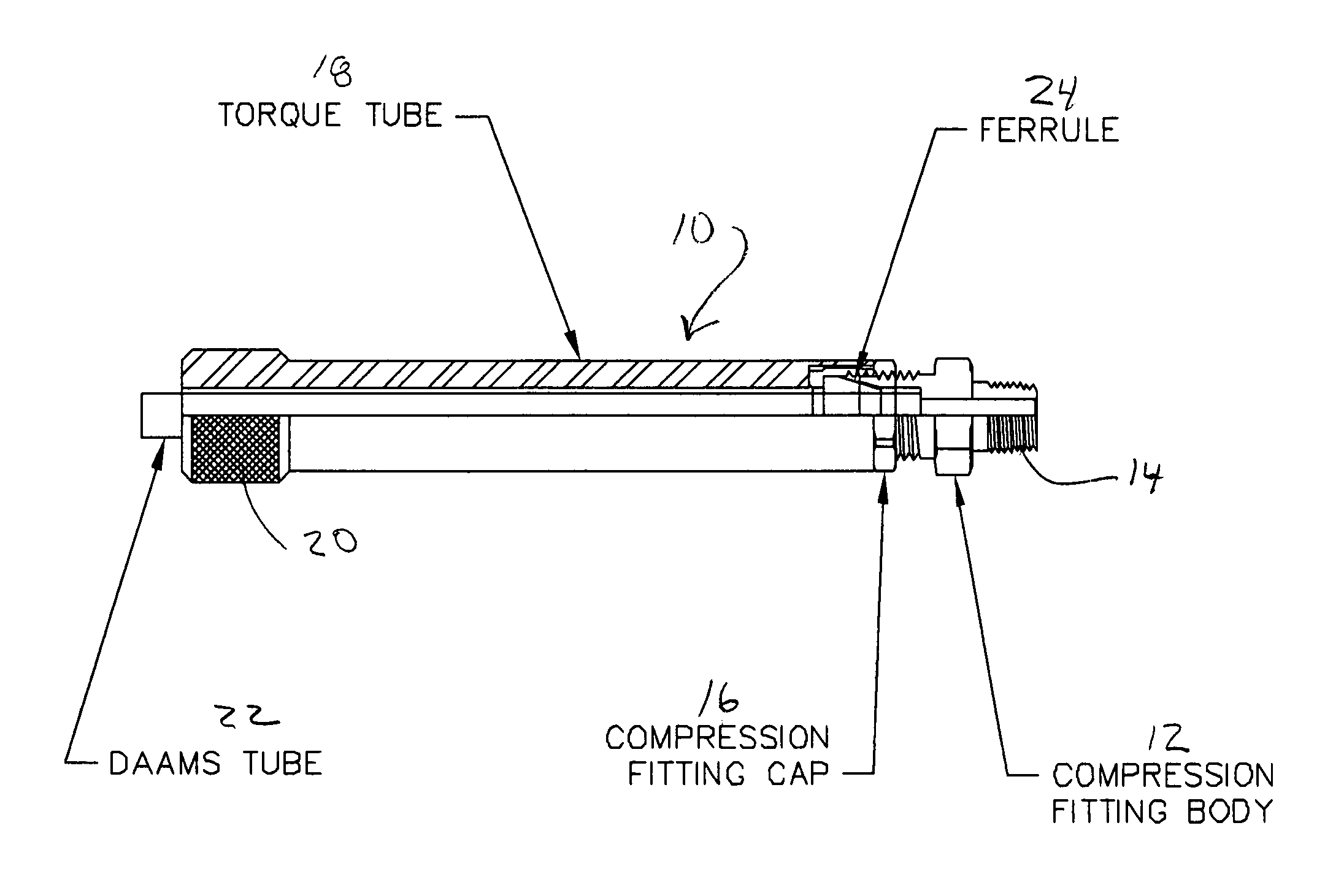
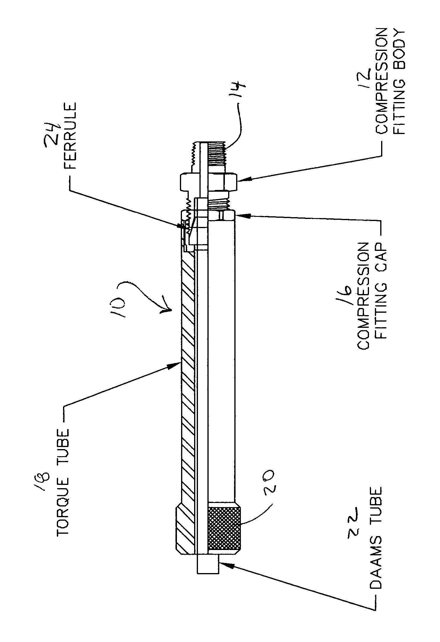
[0012]This invention will be described with reference to the drawing FIGURE where the sample tube holder is shown in a partial cross-sectional view at 10. The tube holder includes a compression fitting body 12 having an end 14 that is adapted for connection to a source of vacuum such as a vacuum manifold (not shown.) End 14 may be threaded as shown in the drawing or may comprise any other gas tight connection means such as a snap coupling or the like. The other end of the compression fitting body 12 is adapted to accept and seat an end of a sample tube and to provide communication between the vacuum source and the seated tube end. Fitting body 12 is threaded for connection to a compression fitting cap 16 that is extended as a torque tube 18. The free end of torque tube 18 opposite fitting cap 16 preferably terminates as a thumb wheel 20. Wheel 20 may be provided with a knurled or otherwise patterned surface for ease in gripping and turning without use of a wrench or other tool.

[0013...


PUM


Abstract

A sorbent-filled sample tube is mounted to an aspirating source using a sample tube holder that includes a compression fitting having a fitting body, a cap, and a ferrule. The fitting cap is extended as a torque tube that surrounds the sample tube and has a length approximately equal to that of the sample tube to thereby protect the sample tube from damage. The free end of the torque tube is formed as a thumb wheel for ease in inserting and removing the sample tube without the use of a wrench or other tool.

Description

REFERENCE TO RELATED APPLICATION[0001]This application claims the benefit of U.S. Provisional Patent Application No. 60 / 692,166 that was filed Jun. 20, 2005.BACKGROUND OF THE INVENTION[0002]1. Technical Field[0003]This invention relates to an improvement in devices for monitoring air and other gases.[0004]More particularly, this invention relates to an improvement to the mounting means for a sampling tube used in an air or industrial gas monitoring system.[0005]2. Description of Related Art[0006]A common method for monitoring air and other gas streams to detect the presence of chemical agents, toxic industrial chemicals, and other compounds that might be of interest employs sorbent-packed tubes for sample collection. Those sample tubes, commonly referred to as DMMS tubes (an acronym for depot area air monitoring system) comprise a glass or stainless steel tube that is filled with a solid adsorbent such as activated carbon or a molecular sieve. The adsorbent filling is selected accor...

Claims


Application Information

Patent Timeline
IPC IPC(8): G01N1/00
CPCG01N1/2214G01N2030/128G01N1/405
Inventor BERENDS, JR., JOHN C.
Owner LEIDOS
Why Eureka
Try Eureka