Supercharge Your Innovation With Domain-Expert AI Agents!

Nose pad for camera

a nose pad and camera technology, applied in the field of nose pads, can solve the problems of difficult to attach the nose pad to the camera, rigid surface of the existing nose pad, unforgiving, etc., and achieve the effect of reducing unnecessary movements and easy manufacturing of the nose pad

Inactive Publication Date: 2009-08-04
KONDO TAKASHI
View PDF4 Cites 0 Cited by
  • Summary
  • Abstract
  • Description
  • Claims
  • Application Information

AI Technical Summary

Benefits of technology

The nose pad provides stable camera holding, reduces unnecessary movement, and can be comfortably used with various camera types, ensuring secure attachment without interfering with camera functions.

Problems solved by technology

Further, there is a case where a user needs to hold the camera and push a shutter simultaneously to catch an object.
Existing types of nose pads need a plenty of space on the surface of the camera, and it makes it difficult to attach the nose pad to the camera.
Therefore, the surface of the existing nose pads tends to be rigid and unforgiving as far as a capacity to fit various shapes of noses.

Method used


Image

  • Nose pad for camera
  • Nose pad for camera
  • Nose pad for camera

Examples


Embodiment Construction

[0025]Hereinafter, preferred embodiments of the invention will be explained with references to the accompanying drawings.

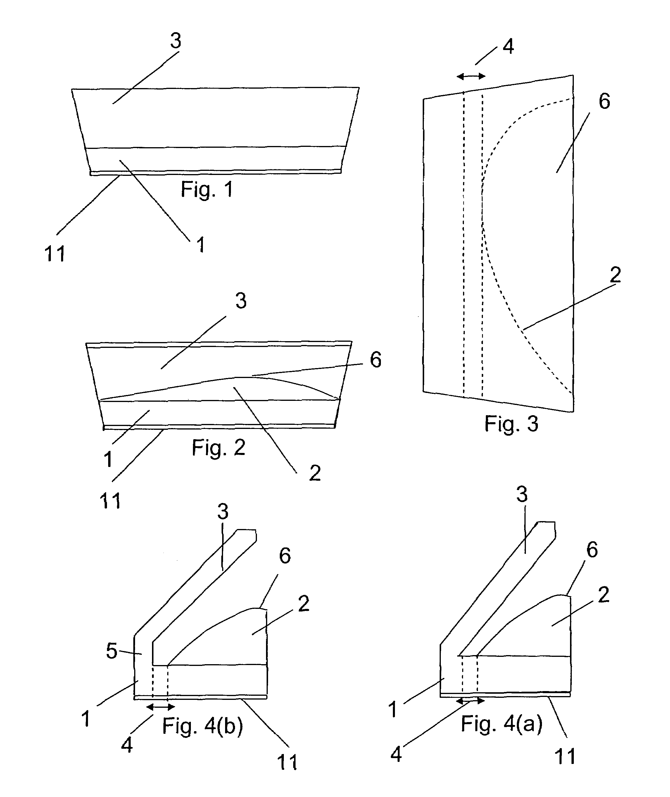
[0026]FIG. 1 is a front view of a nose pad, and FIG. 2 is a rear view of the nose pad, shown in FIG. 1.

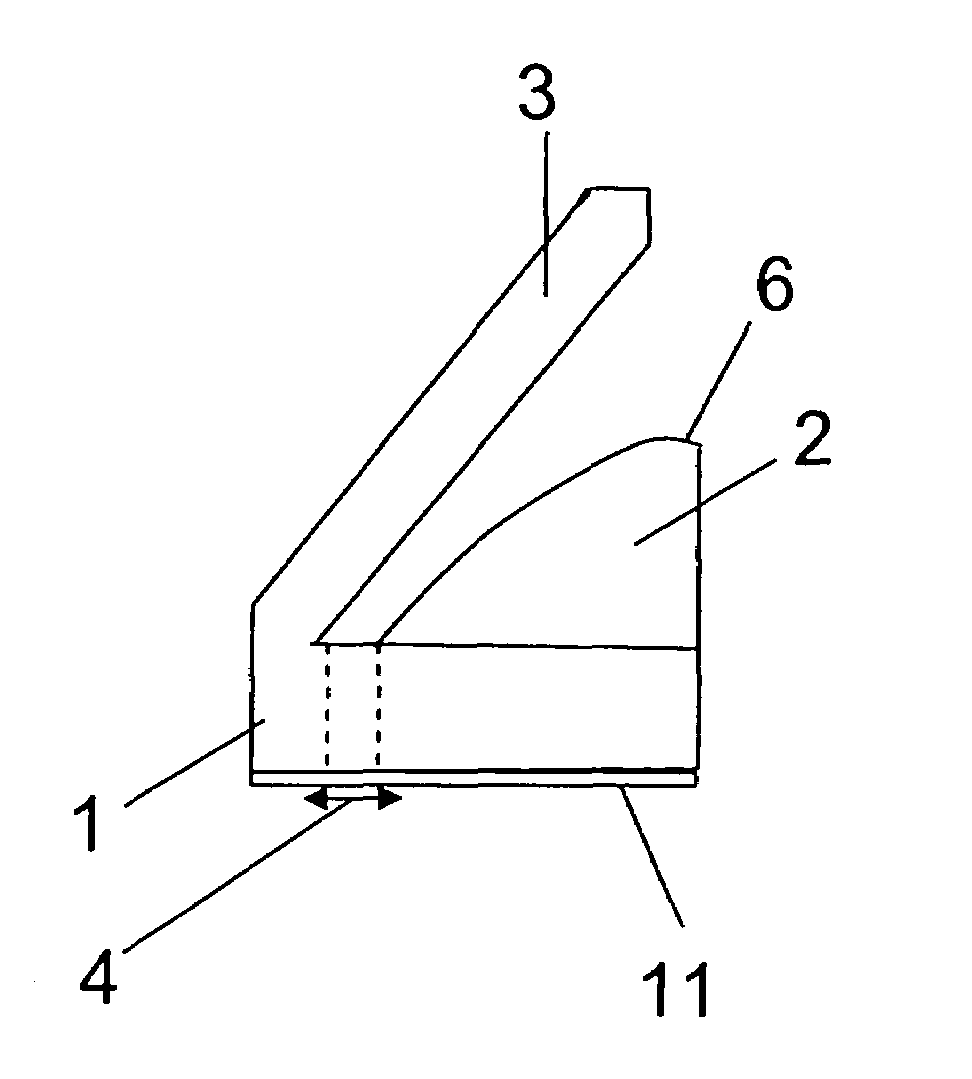
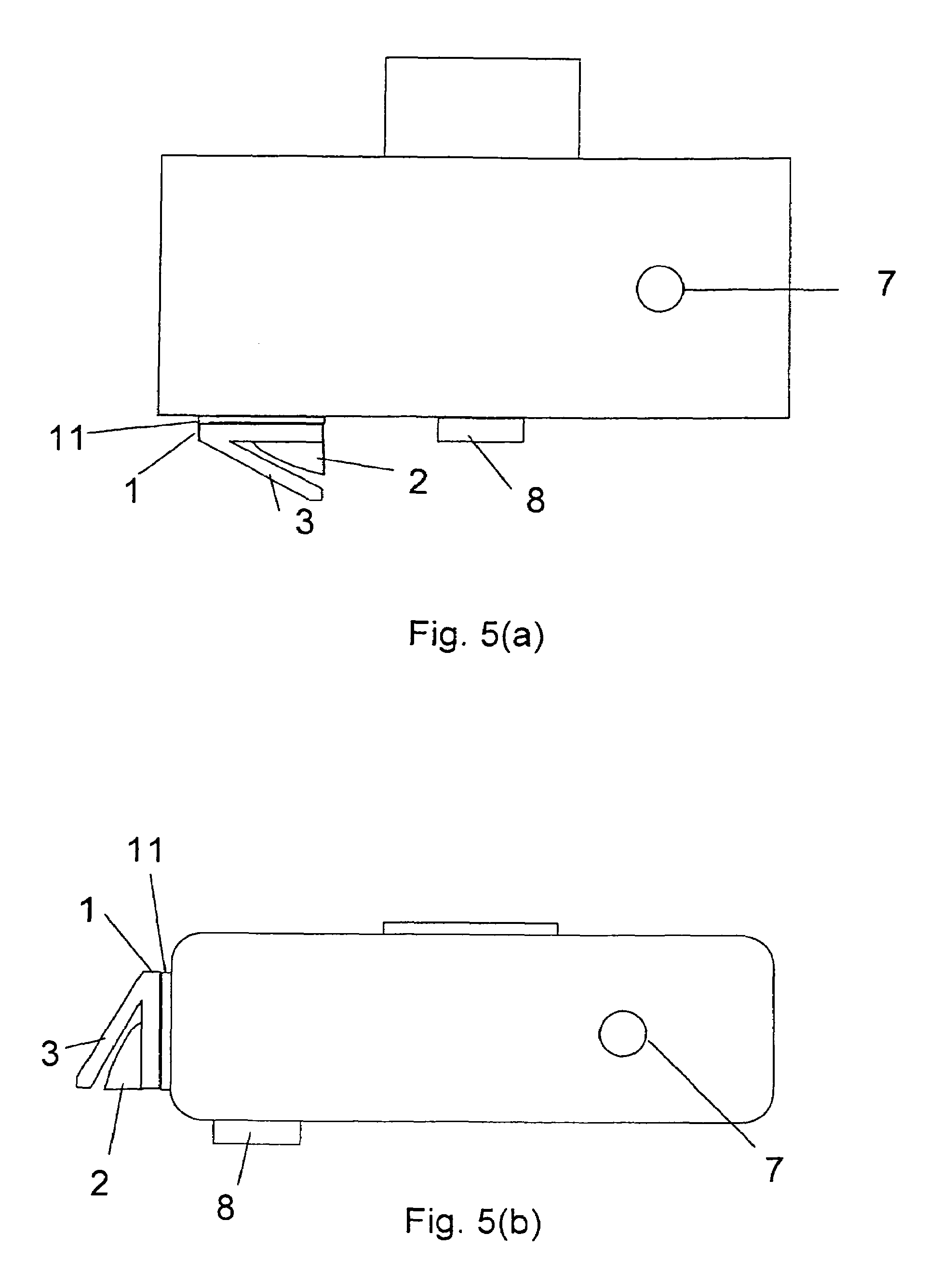
[0027]As shown FIGS. 1 and 2, the embodiment of the invention basically includes a base plate 1, a projecting portion 2 which is designed to fit a contour of a nose and a sheet portion 3. The base plate 1 has a rectangular flat shape to be attached to an outer surface of a camera.

[0028]In the present invention, the projecting portion 2 can be separately formed and bonded onto the base plate, or integrally formed with the base plate 1 as one unit. In FIGS. 1-7, the one unit type of nose pad is employed, even though each of FIGS. 1-7(b) has a line, separating the base plate 1 and the projecting portion 2 for better understanding. An illustration for an embodiment of the separately formed projecting portion bonded to the base plate is omitted since it would be subst...


PUM


Abstract

A nose pad for camera includes a base plate, at least one projecting portion mounted to the base plate, and a sheet portion mounted to an edge of the base plate at an edge of the sheet portion and extending obliquely upwardly over the base plate and the sheet portion. The projecting portion has an arc shape so that the nose pad can fit a contour of a nose. The sheet portion is designed to have a reasonable space in between the sheet portion and the projecting portion, so that the nose of the user can softly touch the camera when the nose pad is used.

Description

BACKGROUND OF THE INVENTION AND RELATED ART STATEMENT[0001]The present invention relates to a nose pad to be attached to a camera for stabilizing the camera when the camera is held in a position to take a picture.[0002]Recently, a camera, especially a digital camera, is provided with a large screen for viewing the object to be taken. In this type of camera, a person holding the camera do not need to attach the person's face to the camera.[0003]However, if a picture is to be taken clearly from a long range or in a very close range, it is preferable to see the object through a finder. In this case, the finder is still used.[0004]In using the finder, it is essential to stabilize and hold a camera horizontally for a good quality of picture.[0005]Further, there is a case where a user needs to hold the camera and push a shutter simultaneously to catch an object. In such a case, it is significantly important to hold the camera stably and horizontally and push the shutter in a very short pe...

Claims


Application Information

Patent Timeline
Patent Type & Authority Patents(United States)
IPC IPC(8): G03B17/00
CPCG03B17/56G03B17/02G03B17/561G03B17/563
Inventor KONDO, TAKASHI
Owner KONDO TAKASHI
Features
  • R&D
  • Intellectual Property
  • Life Sciences
  • Materials
  • Tech Scout
  • Unparalleled Data Quality
  • Higher Quality Content
  • 60% Fewer Hallucinations
Learn More