Supercharge Your Innovation With Domain-Expert AI Agents!

Method for initializing increment position sensor

a technology of position sensor and increment, which is applied in the direction of machines/engines, electrical control, instruments, etc., can solve the problems of system not knowing the position of the increment sensor, undue movement of the sensor and valve, and small information to the system, so as to reduce unnecessary movement

Inactive Publication Date: 2010-03-16
CONTINENTAL AUTOMOTIVE SYST INC
View PDF7 Cites 0 Cited by
  • Summary
  • Abstract
  • Description
  • Claims
  • Application Information

AI Technical Summary

Benefits of technology

[0009]The microcontroller can override initialization of the sensor assembly when a vehicle engine is at a predetermined temperature to allow the components of the intake manifold to reach desired positions prior to initialization. The override of the sensor assembly initialization reduces unnecessary movement for initializing that is immediately followed by moving the actuator to adjust the intake manifold components. Once the intake manifold components reach the desired position the sensor assembly is initialized.

Problems solved by technology

The system does not know what position the increment sensor is at start up.
However, moving the sensor and valves to a default position can create undue movement of the sensor and valves and provides little information to the system regarding the sensor assembly.

Method used


Image

  • Method for initializing increment position sensor
  • Method for initializing increment position sensor
  • Method for initializing increment position sensor

Examples


Embodiment Construction

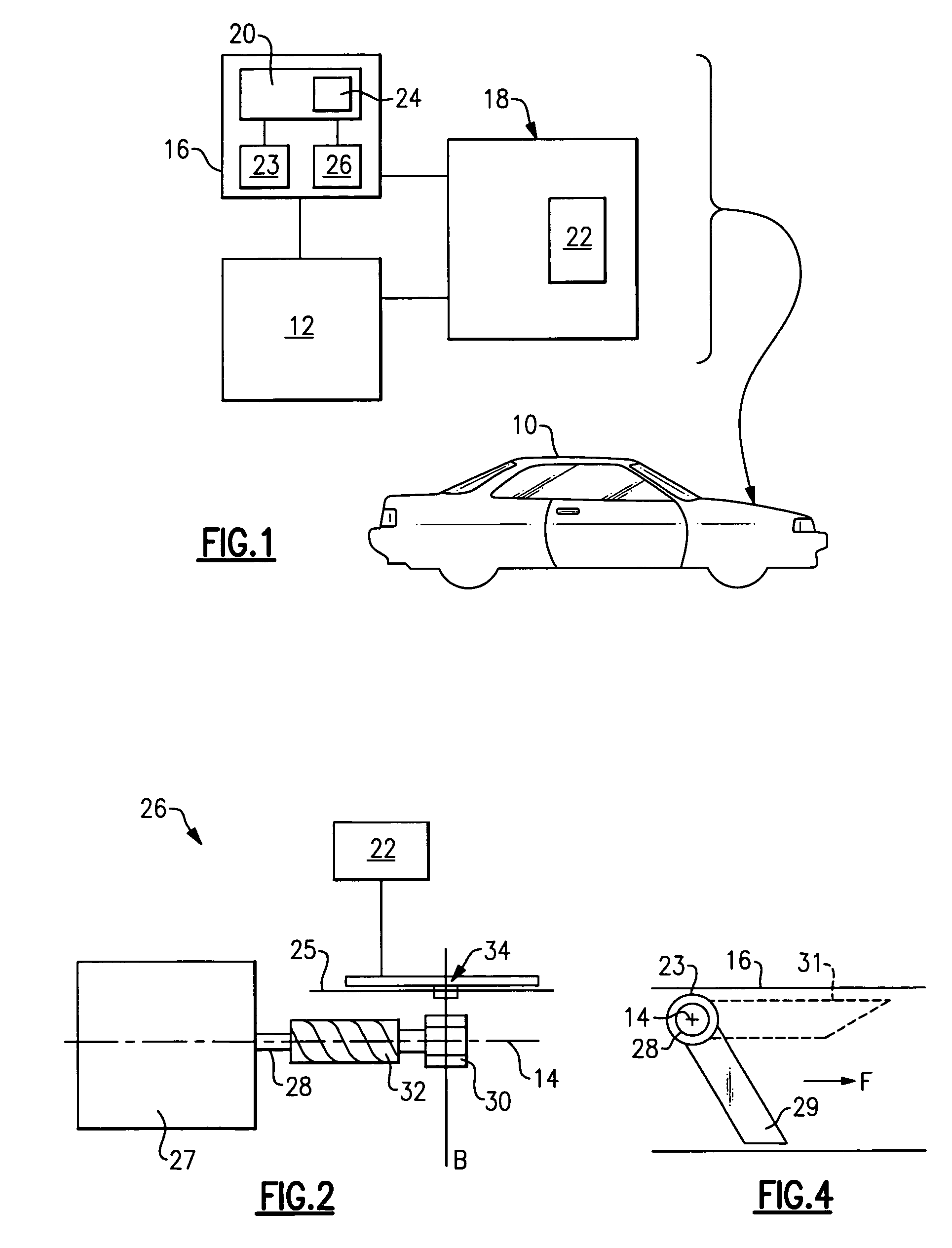
[0015]FIG. 1 illustrates a vehicle 10 having an engine 12 and an intake manifold system 16 connected to a fuel injection system 18. The intake manifold system 16 includes an engine actuator 20. An engine controller 22 within the fuel injection system 18 is connected to the engine actuator 20 to control air delivery to the engine 12.

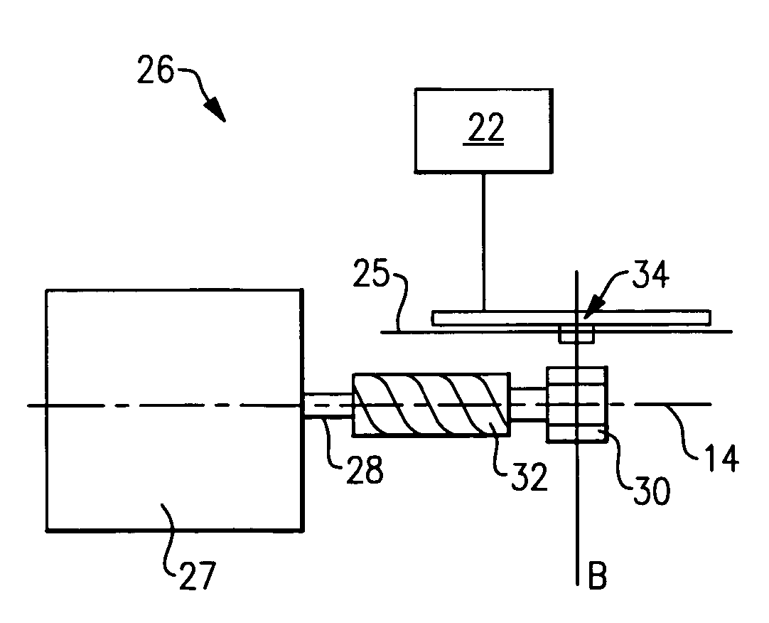
[0016]The engine controller 22 directs the engine actuator 20 to operate valves 23 within the intake manifold 16 to modify the combustion in engine 12. In order to provide the engine 12 with a proper timing for fuel ignition the intake engine controller 22 needs to know information, such as the manifold air pressure and engine actuator 20 position. As the engine 12 speed and temperatures increases, airflow through the intake manifold 16 must be increased. When the speed and temperature of the engine 12 decrease, airflow through the intake manifold 16 must be decreased. The engine actuator 20 adjusts valves inside the intake manifold 16 to optimize air del...


PUM


Abstract

An increment sensor assembly inquires an microcontroller as to the last known increment when a vehicle is started. The last known increment data is used to rotate the sensor backward to reach a lower mechanical stop position or forward to reach an upper mechanical stop position. A timer tracks the sensor to ensure that one of the known stop positions is reached within a predetermined time period or performs a system check to determine what error has occurred. Once the sensor reaches one of the known stop positions an increment counter is reset and the sensor assembly begins normal operation.

Description

[0001]The present invention claims the benefit of U.S. Provisional Patent Application No. 60 / 661,632, filed Mar. 14, 2005.BACKGROUND OF THE INVENTION[0002]This invention relates to an improved system for initializing a position sensor for an engine actuator. More particularly, this invention relates to initializing an incremental position sensor based upon the last know location of the sensor.[0003]Intake manifolds control airflow into a vehicle engine to modify engine performance. Engine actuators are used to control valves within the intake manifold. The valves modify air flow characteristics to enhance engine performance in terms of either fuel economy or torque output. A sensor measures the rotational position of an engine actuator output shaft to determine the position and speed of the valves. The position information is sent to an engine controller which uses the information to adjust the valves. Absolute and increment position sensors are utilized for determining the engine a...

Claims


Application Information

Patent Timeline
Patent Type & Authority Patents(United States)
IPC IPC(8): G01R35/00G01P13/00
CPCF02D41/009G01D5/2451G01D5/24495F02D41/06G01D18/00G01D5/12G01M15/04
Inventor SCHMIDT, JEREMYCRONMILLER, MARK
Owner CONTINENTAL AUTOMOTIVE SYST INC
Features
  • R&D
  • Intellectual Property
  • Life Sciences
  • Materials
  • Tech Scout
  • Unparalleled Data Quality
  • Higher Quality Content
  • 60% Fewer Hallucinations
Learn More