Supercharge Your Innovation With Domain-Expert AI Agents!

Lens barrel and optical device

a technology of optical elements and lens barrels, applied in the field of lens barrels and optical devices, can solve the problems of unfavorable optical element movement, image stabilization may not be properly controlled, image stabilizers are not properly controlled, etc., and achieve the effect of reducing unnecessary movement of optical elements

Inactive Publication Date: 2018-11-06
CANON KK
View PDF4 Cites 0 Cited by
  • Summary
  • Abstract
  • Description
  • Claims
  • Application Information

AI Technical Summary

Benefits of technology

The present invention provides a lens barrel and an optical device that can reduce unnecessary movement of an optical element. This is achieved by using a magnetic body and a first actuator to rotate a second member holding a first magnet and a first optical element. The magnetic body is in contact with the first magnet to reduce magnetic flux density at the adjacent surface of the first magnet, resulting in reduced movement of the optical element. This technology improves the accuracy and stability of optical devices.

Problems solved by technology

However, the image stabilization may not be controlled properly in the image stabilization process of the lens barrel with the plurality of image stabilizers.
As a result, the image stabilizers are not controlled properly in the image stabilizing process.
That is, the conventional lens barrel may move the optical elements unnecessarily due to the magnetic attraction that occurs between the magnets of the adjacent image stabilizers.

Method used


Image

  • Lens barrel and optical device
  • Lens barrel and optical device
  • Lens barrel and optical device

Examples


Embodiment Construction

[0026]Hereafter, embodiments according to the present invention will be described in detail with reference to the drawings.

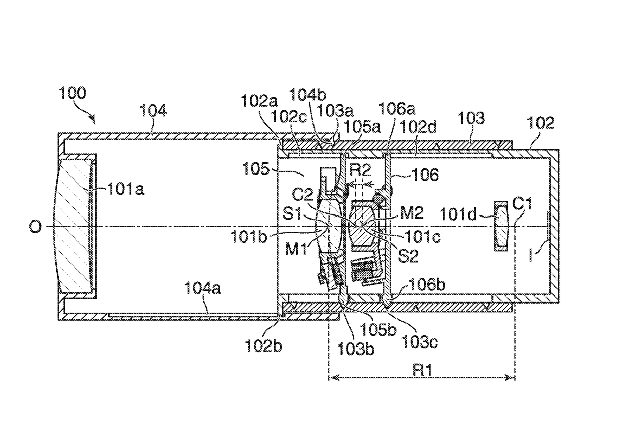
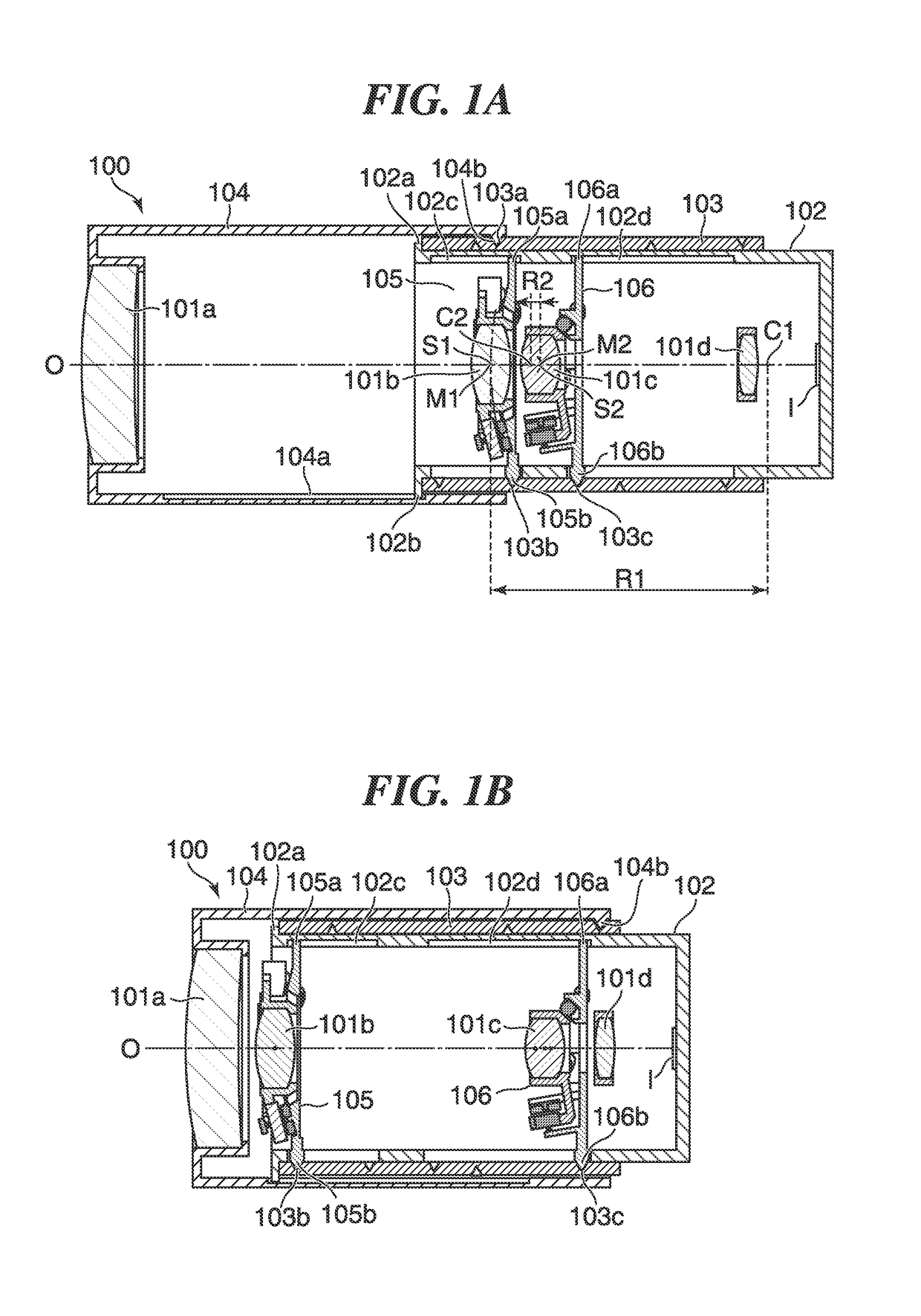
[0027]FIG. 1A is a sectional view schematically showing a configuration of a lens barrel 100 that is an optical device according to an embodiment of the present invention in a TELE state. FIG. 1B is a sectional view schematically showing the configuration of the lens barrel 100 in a WIDE state.

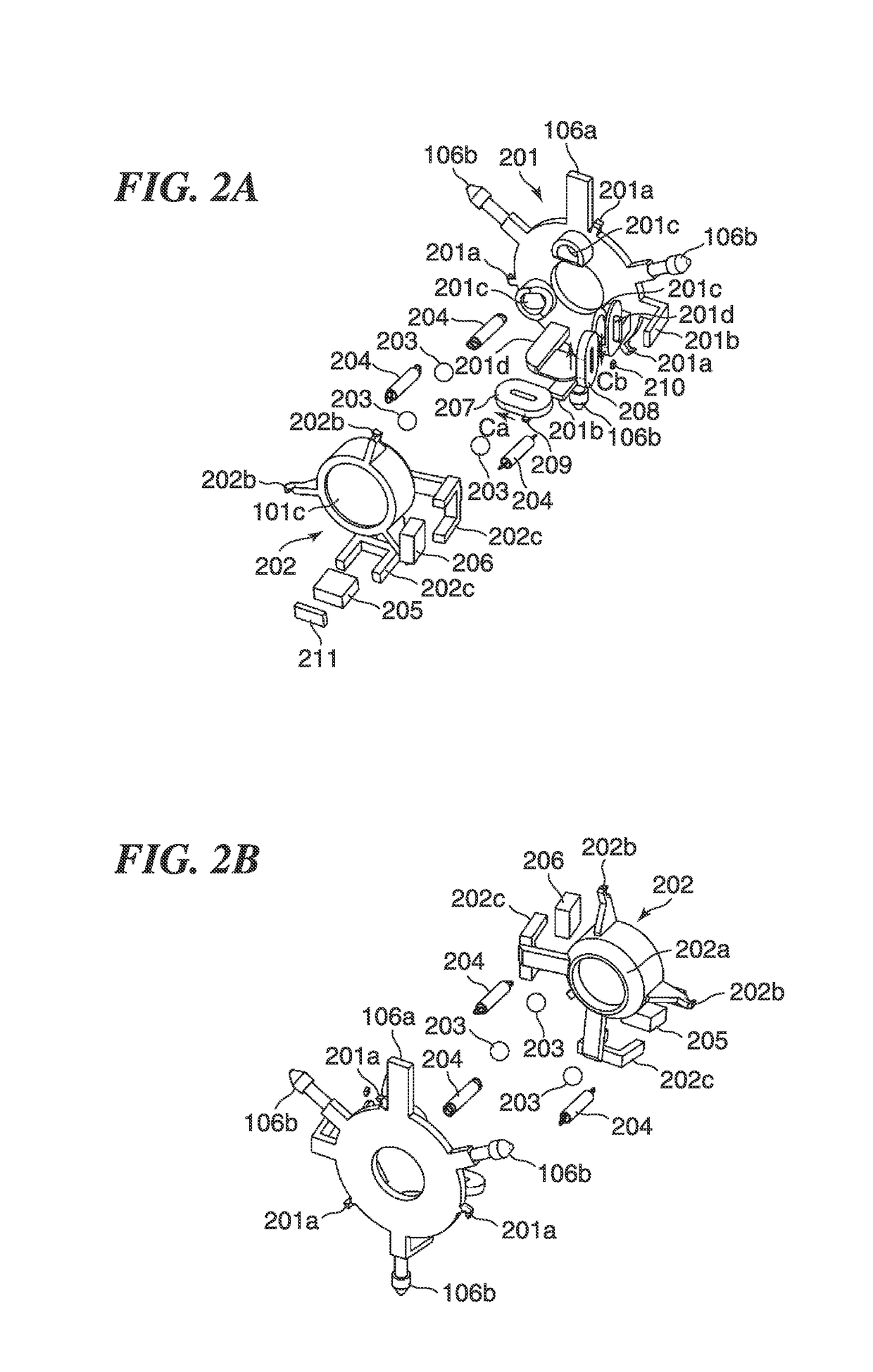
[0028]As shown in FIG. 1A, the lens barrel 100 is provided with a zoom lens 101a, focusing lens 101d, guide barrel 102, cam ring 103, zoom lens barrel 104, first image stabilizer (first unit) 105, and second image stabilizer (second unit) 106. The first image stabilizer 105 is provided with a first correction lens (first optical element) 101b. The second image stabilizer 106 is provided with a second correction lens (second optical element) 101c.

[0029]The zoom lens 101a, first correction lens 101b, second correction lens 101c, and focusing lens 101d are arranged along an ...


PUM


Abstract

A lens barrel that is capable of reducing unnecessary movement of an optical element. A first unit has a first correction optical element arranged on an optical axis and a first magnet that moves the first correction optical element along a first spherical surface around a first point on the optical axis. A second unit has a second correction optical element arranged on the optical axis and a second magnet that moves the second correction optical element along a second spherical surface of which radius is smaller than the radius of the first spherical surface around a second point on the optical axis. A magnetic body is arranged on at least one of the first unit and the second unit, and reduces leakage of magnetic flux from a facing part of the second magnet that faces the first magnet.

Description

BACKGROUND OF THE INVENTION[0001]Field of the Invention[0002]The present invention relates to a lens barrel and an optical device, and in particular, relates to the lens barrel and the optical device that are capable of correcting a blur of an image formed on an imaging plane.[0003]Description of the Related Art[0004]There are some lens barrels that have optical systems for forming an image on an image plane and image stabilizers for reducing a blur of the image formed on the image plane by moving a correction lens as an optical element included in the optical system concerned. An image stabilizer is provided with a magnet and a coil for moving a correction lens. When electric current is applied to the coil, electromagnetic force that acts between the magnet and the coil moves the correction lens along a spherical surface of which the center is a point on an optical axis, which corrects a blur of the image formed on the image plane (for example, see Japanese Laid-Open Patent Publica...

Claims


Application Information

Patent Timeline
Patent Type & Authority Patents(United States)
IPC IPC(8): G02B27/64G02B7/10
CPCG02B7/102G02B27/646
Inventor KIYAMURA, KOUSUKE
Owner CANON KK
Features
  • R&D
  • Intellectual Property
  • Life Sciences
  • Materials
  • Tech Scout
  • Unparalleled Data Quality
  • Higher Quality Content
  • 60% Fewer Hallucinations
Learn More