Fluid bed reactor having vertically spaced apart clusters of heating conduits

a technology of heating conduits and flue beds, which is applied in the direction of muffle furnaces, bulk chemical production, furnaces, etc., can solve the problems of low heat supply, poor reactor performance, and starvation of feedstock injection regions

Active Publication Date: 2009-08-04
THERMOCHEM RECOVERY INT
View PDF22 Cites 69 Cited by
  • Summary
  • Abstract
  • Description
  • Claims
  • Application Information

AI Technical Summary

Problems solved by technology

An issue in the prior art configuration is that drying, devolatilization, char formation and char conversion processes all compete for heat transfer and mass transfer in the region that is above the distributor but below the bottom pulse heater.
The only link is the solids circulation rate and if this is not up to par, the feedstock injection region starves for heat and the reactor performance suffers.
Due to feedstock injection and reduced solids circulation rate, the heat supply is limited which is likely to depress the char temperature and in turn the char conversion rate.
In the region of the pulse heaters, the heat transfer is good but the mass transfer may be unsatisfactory if the reactant (steam) bypasses due to channeling, again impairing char conversion.
Operating these units in bubbling fluidization regime is rather limiting from heat and mass transfer and gas / solid contact standpoints due to the relatively large bubbles, increased bubble coalescence and the propensity for steam / gas bypassing.
This, however, requires a significantly higher superficial fluidization velocity than that for the bubbling regime.

Method used


Image

  • Fluid bed reactor having vertically spaced apart clusters of heating conduits
  • Fluid bed reactor having vertically spaced apart clusters of heating conduits
  • Fluid bed reactor having vertically spaced apart clusters of heating conduits

Examples


Embodiment Construction

[0022]The contents of U.S. Pat. Nos. 5,059,404; 5,306,481; 5,353,721; 5,536,488; 5,637,192 and 6,149,765 are incorporated by reference to the extent necessary to understand the present invention.

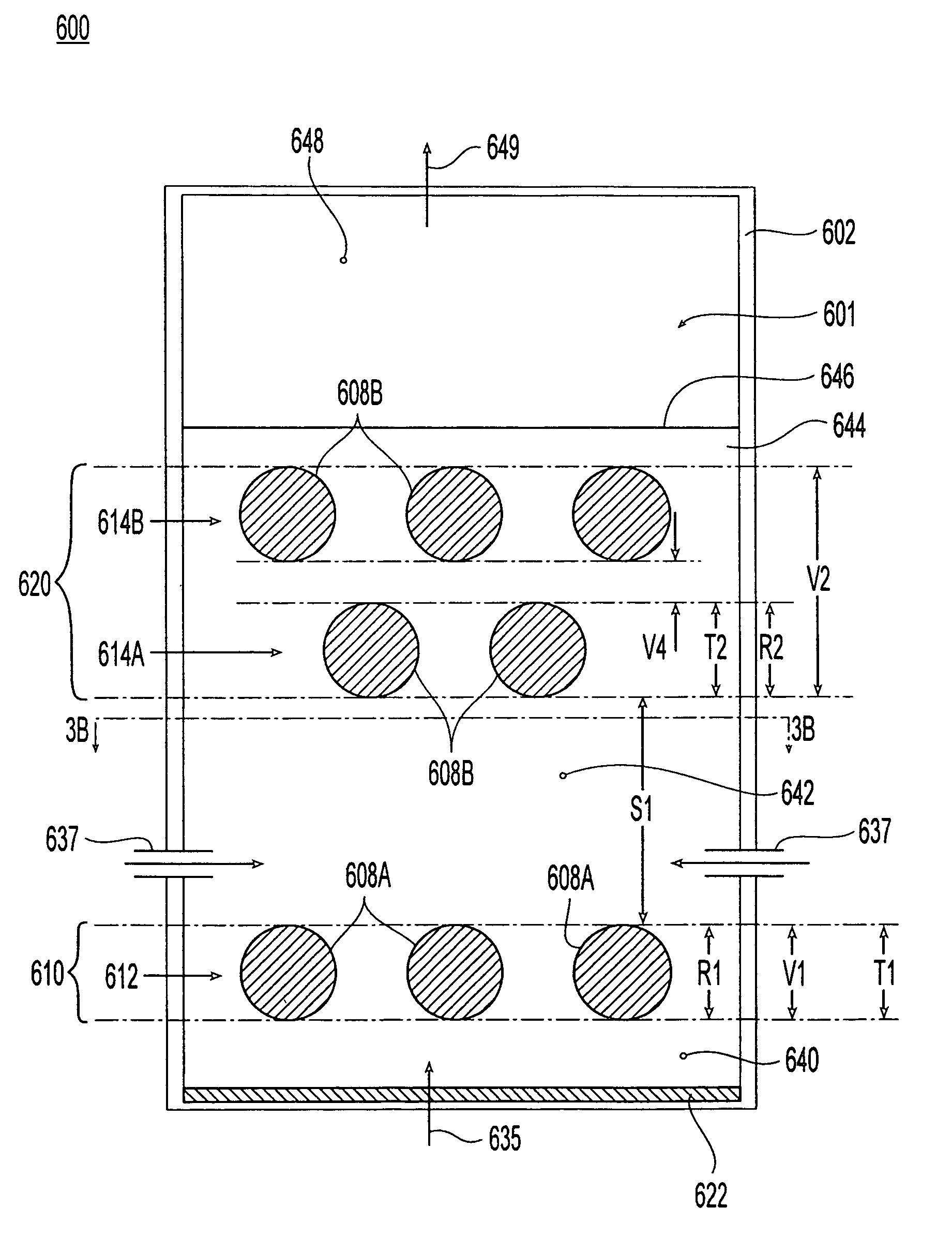
[0023]FIGS. 3A and 3B show views of a fluid bed reformer 600 comprising a compartment 601 serving as a reaction vessel 602. As best seen in FIG. 3B, the reaction vessel 602 has a rectangular footprint (i.e., a rectangular shape in a horizontal cross-section) comprising two long sides 604A, 604B and two short sides 606A, 606B. A plurality of pulse heaters 608A, 608B pass through the long sides 604A, 604B of the reformer vessel 600. In one embodiment, the pulse heaters 608A, 608B are of a sort well known to those skilled in the art, such as those disclosed in U.S. Pat. No. 5,059,404, mentioned above. The resonance tubes 609 associated with these pulse heaters 608A, 608B serve as heating conduits for indirectly heating contents of the compartment 601.

[0024]The pulse heaters 608A, 608B are organ...


PUM

PropertyMeasurementUnit
height H1aaaaaaaaaa
height H2aaaaaaaaaa
thicknessaaaaaaaaaa

Abstract

A fluid bed reactor is configured to process a reactive material to form one or more products. The reactor includes a reaction vessel defining a compartment configured to receive the reactive material. A first cluster of heating conduits at least partially occupies the compartment and extends over a first vertical extent within the compartment. A second cluster of heating conduits partially occupies the compartment and extends over a second vertical extent within the compartment. The first cluster of heating conduits is vertically below the second cluster of heating conduits and spaced apart therefrom by a first separation distance. Feedstock inlets are configured to introduce the reactive material into a region that is vertically between the first and second clusters of heating conduits. The heating conduits in the first cluster have a first thickness while the heating conduits in the second cluster have a second thickness. The first separation distance is at least as great as the smaller of the first and second thicknesses.

Description

FIELD OF THE INVENTION[0001]The present invention relates to a fluid bed reactor for processing a reactive material, which may include inorganic materials, and also carbonaceous materials, such as black liquor and biomass, to process and / or recycle materials and extract energy. More particularly, the present invention concerns such a reactor having two or more spaced apart clusters of heating conduits configured to indirectly heat the fluid bed and materials therein.BACKGROUND OF THE INVENTION[0002]FIGS. 1A and 1B show top and side views, respectively, of a prior art reactor, configured as a cylindrical reformer 100. The cylindrical reformer 100 includes a cylindrical compartment 101 forming a reaction vessel. The reformer 100 comprises one or more pulse heaters 102A, 102B, each of which comprises a pulse combustor 104A, 104B connected to a respective resonance tube 106A, 106B. As seen in FIG. 1A, the pulse heaters 102A, 102B extend in one direction across the diameter of the cylind...

Claims


Application Information

Patent Timeline
Patent Type & Authority Patents(United States)
IPC IPC(8): B01J7/00B01J8/18C01B3/36C10J3/46C10J3/54F27B15/00F27B15/14F27B15/16F28D13/00H01M8/06
CPCC10B47/24C10J3/482C10J3/56C10J3/723F27B15/14F27B15/02F27B15/10C10J2300/1261C10J2300/0973Y02P20/52
Inventor CHANDRAN, RAVI
Owner THERMOCHEM RECOVERY INT
Why Eureka
Try Eureka