Relative configuration of an engine intake pipe for a motorcycle

a technology of relative configuration and intake pipe, which is applied in the direction of machines/engines, liquid fuel feeders, and combustion air/fuel-air treatment, etc. it can solve the problems of body frame and fuel injector twitching each other, and achieve the effect of facilitating the space for fuel injector placement, preventing interference between the body frame and the fuel injector of the off-road motorcycle, and facilitating the connection of fuel injector and fuel pump

Active Publication Date: 2009-08-11
YAMAHA MOTOR CO LTD
View PDF13 Cites 14 Cited by
  • Summary
  • Abstract
  • Description
  • Claims
  • Application Information

AI Technical Summary

Benefits of technology

[0009]As described above, the engine is disposed with its cylinder axis inclined rearward such that a center of gravity of the engine is located rearward and is close to a center of gravity of the vehicle that is rearward relative to the center of gravity of the engine. Therefore, the moment of inertia about the center of gravity of the vehicle is reduced and maneuverability of the vehicle is improved. In addition, the intake pipe is provided on the forward side of the engine disposed with its cylinder axis inclined rearward, which creates a space around the intake pipe provided on the forward side of the engine. This readily allows a connecting part of the intake pipe, which is in a straight form, to connect to the engine. Further, the fuel injector is mounted on a rearward side of the intake pipe relative to a forward side where the body frame is disposed, which prevents interference between the fuel injector and the body frame. This eliminates the need for a curved part in the intake pipe designed to prevent interference between the fuel injector and the body frame. Therefore, the connecting part of the intake pipe connected to the engine can be in a straight form to reduce air intake resistance and improve engine performance.
[0026]The vehicle according to the invention may be an off-road motorcycle. With the construction described above, interference between the body frame and the injector of the off-road motorcycle is prevented.

Problems solved by technology

This, however, leads to a problem that the body frame and fuel injector tend to interfere with each other.

Method used


Image

  • Relative configuration of an engine intake pipe for a motorcycle
  • Relative configuration of an engine intake pipe for a motorcycle
  • Relative configuration of an engine intake pipe for a motorcycle

Examples


first embodiment

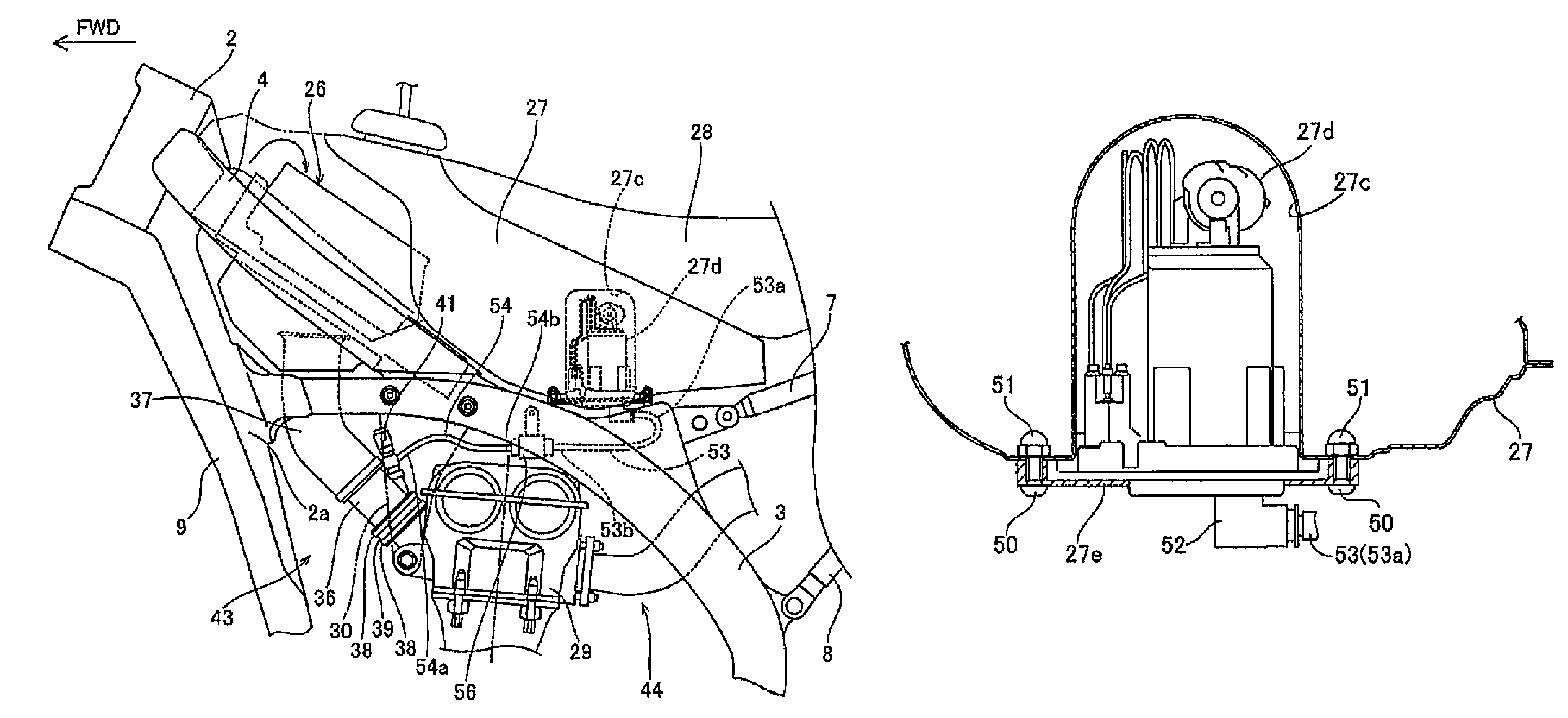
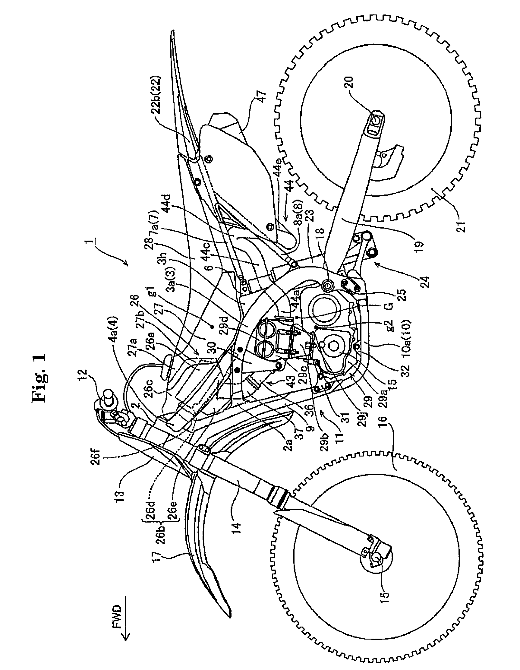
[0042]FIGS. 1-12 illustrate a motorcycle 1 according to a first embodiment of the invention. An off-road motorcycle 1 is described as an example of the vehicle of the invention. The direction indicated by arrow FWD in the drawings is a forward traveling direction of motorcycle 1. In the following description, directions such as “left”, “right”, “forward”, “rearward”, “up”and “down” are from the perspective of a rider facing forward (in the direction of arrow FWD).

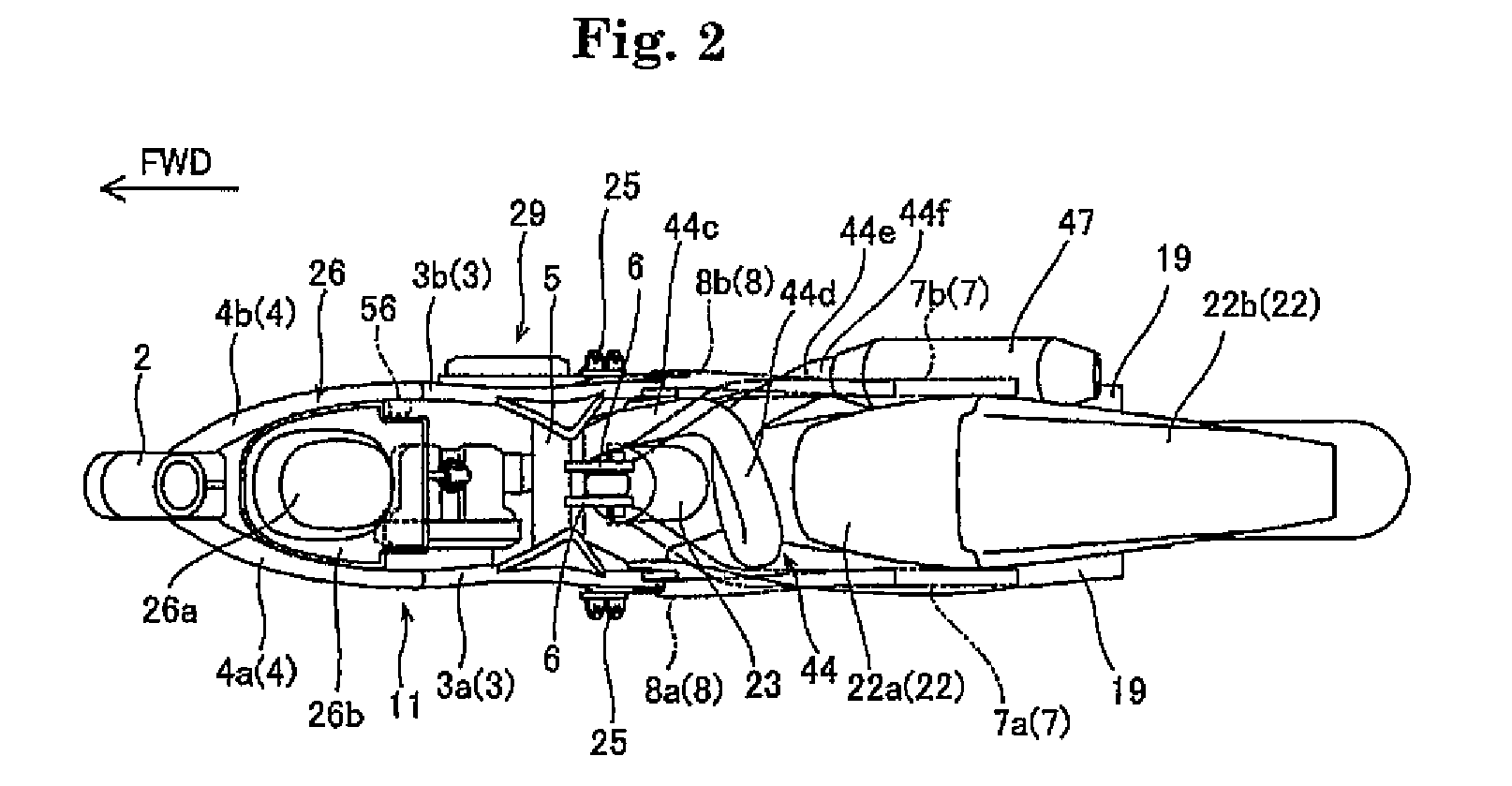
[0043]Motorcycle 1 includes a body frame 11 comprising a head pipe 2, a main frame 3, a tank rail 4, a seat rail 7, a backstay 8, a down tube 9 and a bottom frame 10. As shown in FIG. 1, left and right frames 3a and 3b (FIG. 2) of main frame 3 are connected to a connecting part 2a or a rear part of a head pipe 2. Frames 3a and 3b extend downward to the rear and pass over engine 29 in a longitudinal direction. Left and right tank rails 4a and 4b of tank rail 4 are located between a rear part of head pipe 2 and a top part of ...

second embodiment

[0076]FIG. 13 illustrates a motorcycle according to a second embodiment of the present invention. In the second embodiment, an example is described where two fuel injectors are provided.

[0077]As shown in FIG. 13, a throttle body 60 extending obliquely upward in a straight form is fastened to coupling member 39 on an upstream side by band member 38. Throttle body 60 is an example of the “connecting part of intake pipe” of the present invention. Throttle valve 40 adjusts the amount of air to flow through intake port 29e and is disposed within throttle body 60. Fuel injectors 61 and 62 supply fuel (gasoline) to engine 29 and are attached to throttle body 60.

[0078]In the second embodiment of the invention, fuel injectors 61 and 62 are both mounted on a rearward side of throttle body 60 relative to a forward side where down tube 9 is disposed. Fuel injector 61 is mounted upstream of throttle valve 40 in throttle body 60, while fuel injector 62 is mounted downstream of throttle valve 40. ...


PUM


Abstract

A vehicle has a body frame that does not interfere with an injector. A down tube extends downward to the rear. An engine is disposed with its cylinder axis inclined rearward. An intake pipe located between the down tube and the engine extends obliquely upward from a forward side of the engine. A fuel injector is attached to the intake pipe. The intake pipe includes a straight throttle body connected to the engine. The fuel injector is mounted on a rearward side of the throttle body relative to a forward side where the down tube is disposed.

Description

RELATED APPLICATIONS[0001]This application claims the benefit of priority under 35 USC 119 of Japanese patent application no. 2007-022580, filed on Feb. 1, 2007, and Japanese patent application no. 2008-003727, filed on Jan. 10, 2008, which applications are hereby incorporated by reference in their entireties.BACKGROUND OF THE INVENTION[0002]1. Field of the Invention[0003]The present invention relates to a vehicle having an intake pipe.[0004]2. Description of Related Art[0005]A vehicle having an intake pipe is known. JP-A-2005-529030, for example, discloses a motorcycle having a body frame extending downward to the rear; an engine oriented with its cylinder axis angled rearward; an intake pipe connected to a front side of the engine; and a fuel injector attached to the intake pipe. The body frame passes on the upper side of the intake pipe, and the injector is attached to the upper side of the intake pipe.[0006]Thus, in JP-A-2005-529030, the body frame and injector are both located ...

Claims


Application Information

Patent Timeline
Patent Type & Authority Patents(United States)
IPC IPC(8): F02M61/14F02M37/04
CPCF01N13/20F02M35/10039F02M35/10111F02M69/044F02M35/10216F02M35/162F02M69/043F02M35/10177F01N13/085
Inventor MIYASHIRO, SHIDEHIKO
Owner YAMAHA MOTOR CO LTD
Why Eureka
Try Eureka