
Toolless locking mount

a technology of locking mount and locking plate, which is applied in the direction of washstands, instruments, scaffold accessories, etc., can solve the problems of no universal mount that allows easy installation and removal

Inactive Publication Date: 2009-08-11
THOMPSON
View PDF11 Cites 2 Cited by
  • Summary
  • Abstract
  • Description
  • Claims
  • Application Information

AI Technical Summary

Benefits of technology

[0007]This invention provides a mount that operates quickly and easily. It enables installation or removal of electronic components, laptop computers, etc. with very little effort. This invention, at the most fundamental level, secures an object being mounted on multiple planes thereby preventing both horizontal and vertical movement of the mounted object.
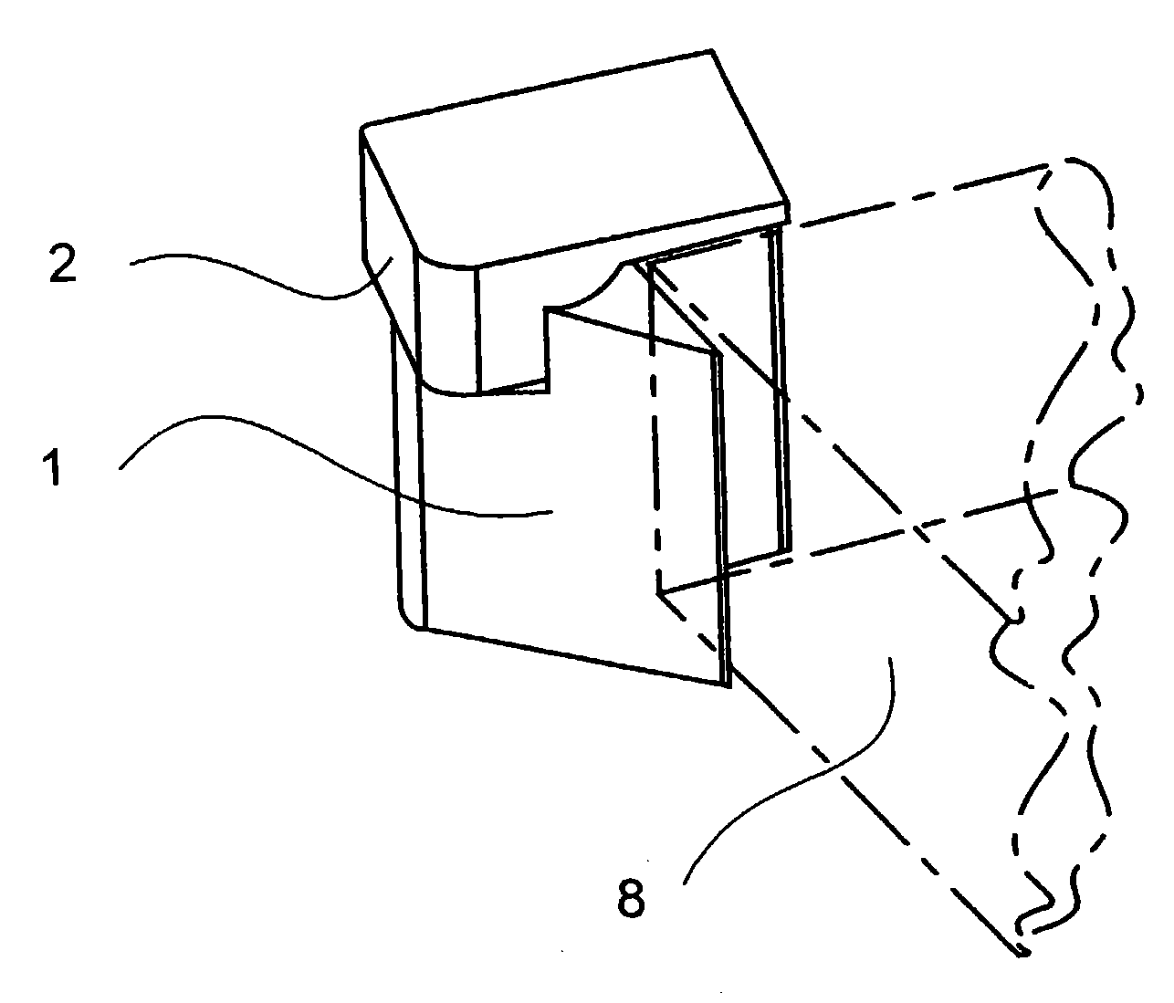
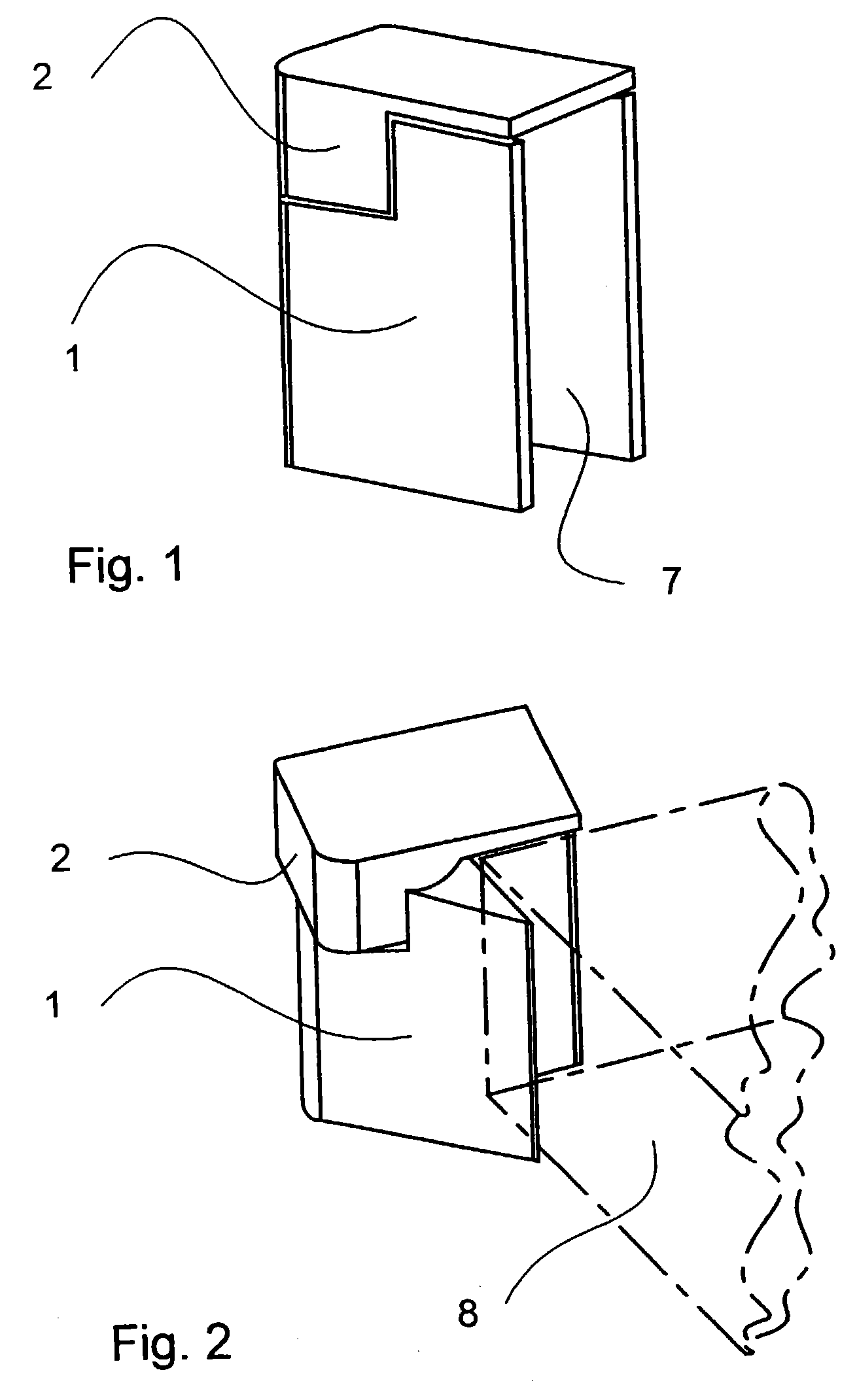
[0008]This mounting mechanism provides uprights with a surface area on two intersecting vertical planes and one horizontal plane. The surface on the horizontal plane swings aside, allowing the mounted object to slide up and away along the vertical planes thus releasing the object. These uprights serve two functions: they prevent side movement of the objects being mounted, and they have a small cap that rotates over the object to either allow vertical movement of the mounted object for removal or prevent the movement thus keeping the object surely in place.
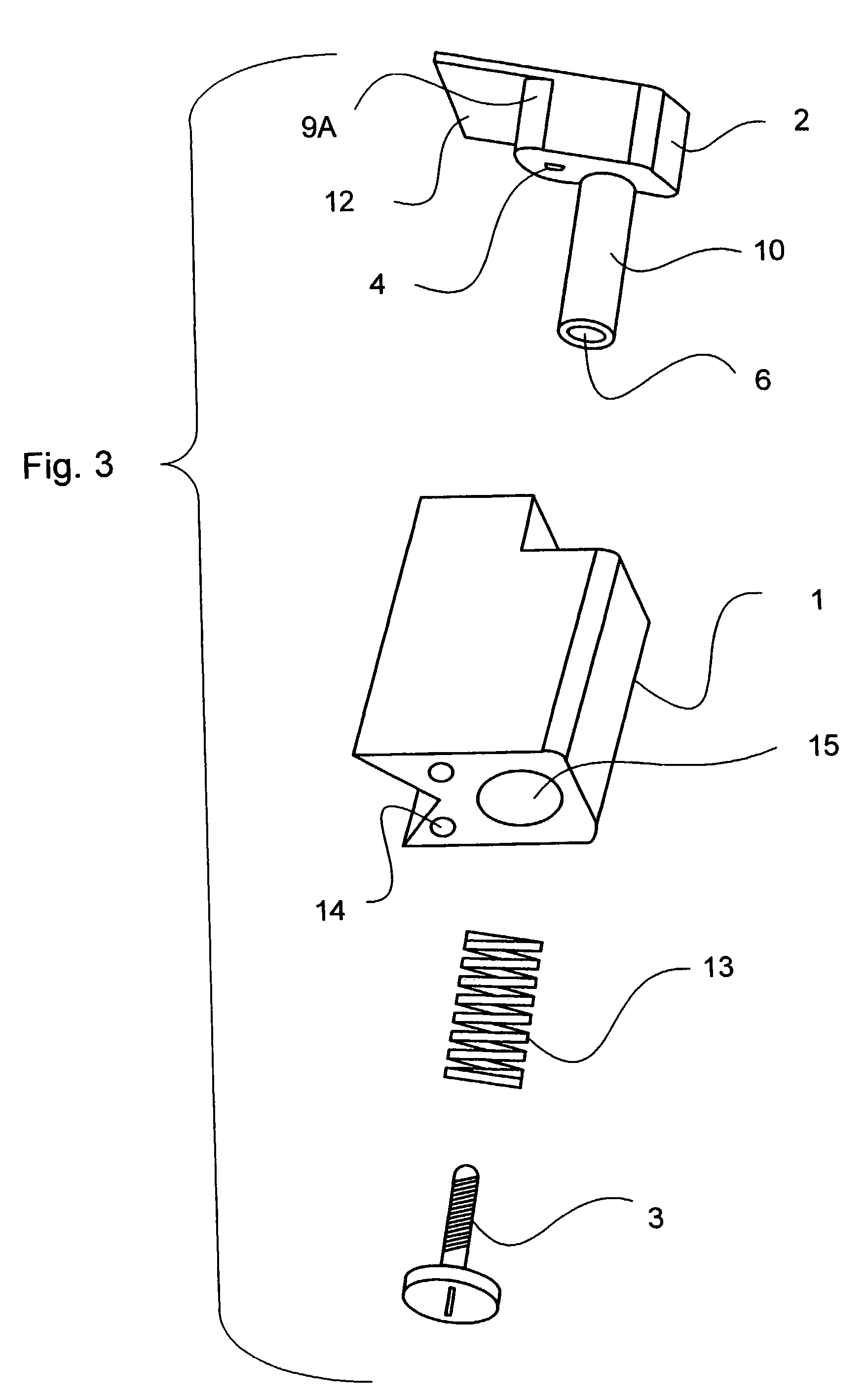
[0010]The mount consists of two main parts—a top and a base. The top rotates over the base and locks it into either a closed or open position. The open position can be either to the right or the left. However, the open position goes only as far as necessary to allow the secured object to be released from the mount. This way the top itself never releases from the base of the mount, nor does it open so wide as to interfere with other objects near it. A spring inside the mount provides enough pressure to prevent the mount from moving inadvertently while at the some time allowing the user of the mount to open it without tools.

Problems solved by technology

However, none have provided a universal mount that allows easy installation and removal without use of tools and securely holds the object to be mounted even if it is inverted.

Method used


Image

  • Toolless locking mount
  • Toolless locking mount
  • Toolless locking mount

Examples


Embodiment Construction

[0018]Turning now to the drawings, wherein like reference numerals indicate identical or corresponding parts, and more particularly to FIGS. 1-3 thereof, a mounting mechanism in accordance with this invention is shown having a base 1 on the top of which is pivotally mounted a top 2. The underside of the top 2 has a nub 4 that clicks into one of three shallow notches 5 in the top surface of the base 1, shown in FIG. 4. The nub 4 facilitates the locking functionality of the mounting mechanism by clicking into the one of three positions, as described in more detail below. The center notch has two sloping sides, and the two end notches have a sloping side on the side adjacent the center notch, and a vertical side on the other side, opposite the sloping side. The notches hold the nub 4 in any of the three positions represented by the position of the notches, but the sloping sides of the notches 5 enable the nub 4 to slide up and over the notches 5 when the top is turned by hand from one ...


PUM


Abstract

A universal mounting mechanism for holding objects, such as electrical, medical, optical or audio / visual components needing secure physical connection to another surface in such a way that the mounted object can be easily and quickly installed and removed. It locks the object by providing surfaces on three planes that firmly engage the object so it does not move during transportation or when mounted on a fixed surface. It is low in profile so it does not obstruct the use of the items being held. The mount has no loose parts that can be lost during installation or removal of the mounted objects. Furthermore, the mount has the added feature of locking into either the open or closed position. Because the range of motion is limited, the top of the mount will not move into a position where it could be damaged or obstruct the use of adjacently mounted items.

Description

[0001]This application is related to U.S. Provisional Application No. 60 / 177,757 filed on Jan. 24, 2000 and entitled “Toolless Locking Mount” and is a division of application Ser. No. 09 / 769,187 filed Jan. 24, 2001, now U.S. Pat. No. 6,592,088 issued Jul. 15, 2003.BACKGROUND OF THE INVENTION[0002]1. Field of the Invention[0003]This invention relates to a physical mounting mechanism designed to act as a support for any objects, electronic or otherwise that need to be secured for movement or transport. The invention not only secures items during transport, but it also allows an easy-open and easy-close capability for quick installation or removal of the mounted object. The mount functions as a support for electronics, mobile computers, and medical equipment where ease of installation and removal, and security of attachment are important.[0004]2. Background Art[0005]Mounts of many types have been designed and created. However, none have provided a universal mount that allows easy insta...

Claims


Application Information

Patent Timeline
Patent Type & Authority Patents(United States)
IPC IPC(8): F21V17/06E05D11/10F16M11/04F16M13/00G06F1/16G06F1/18
CPCF16M11/04F16M11/041F16M13/02G06F1/181F16M13/00E05D11/1078E05Y2900/606Y10T403/591Y10T403/44
Inventor THOMPSON
Owner THOMPSON
Learn More