
Vehicle passenger restraint system

a passenger seat and seat belt technology, applied in the direction of vehicular safety arrangements, vehicle components, pedestrian/occupant safety arrangements, etc., can solve the problems of troublesome design of the storage space layout of the frontward airbag, the restraining force of the seat belt is usually inevitable large, and the design freedom of the steering wheel is reduced, and the storage space is large. , to achieve the effect of reducing the design freedom of the steering wheel, reducing the restraining force of the seat bel

Inactive Publication Date: 2009-08-11
NISSAN MOTOR CO LTD
View PDF14 Cites 24 Cited by
  • Summary
  • Abstract
  • Description
  • Claims
  • Application Information

AI Technical Summary

Benefits of technology

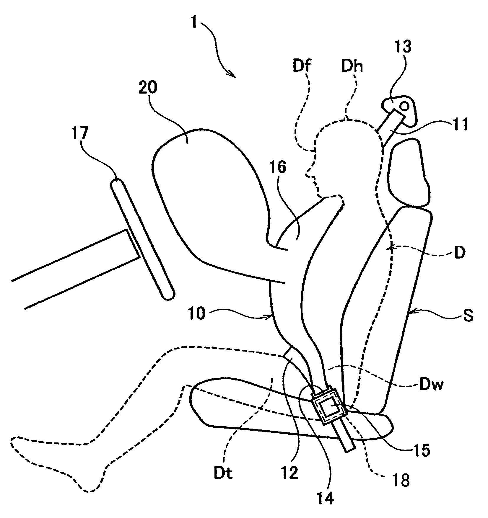
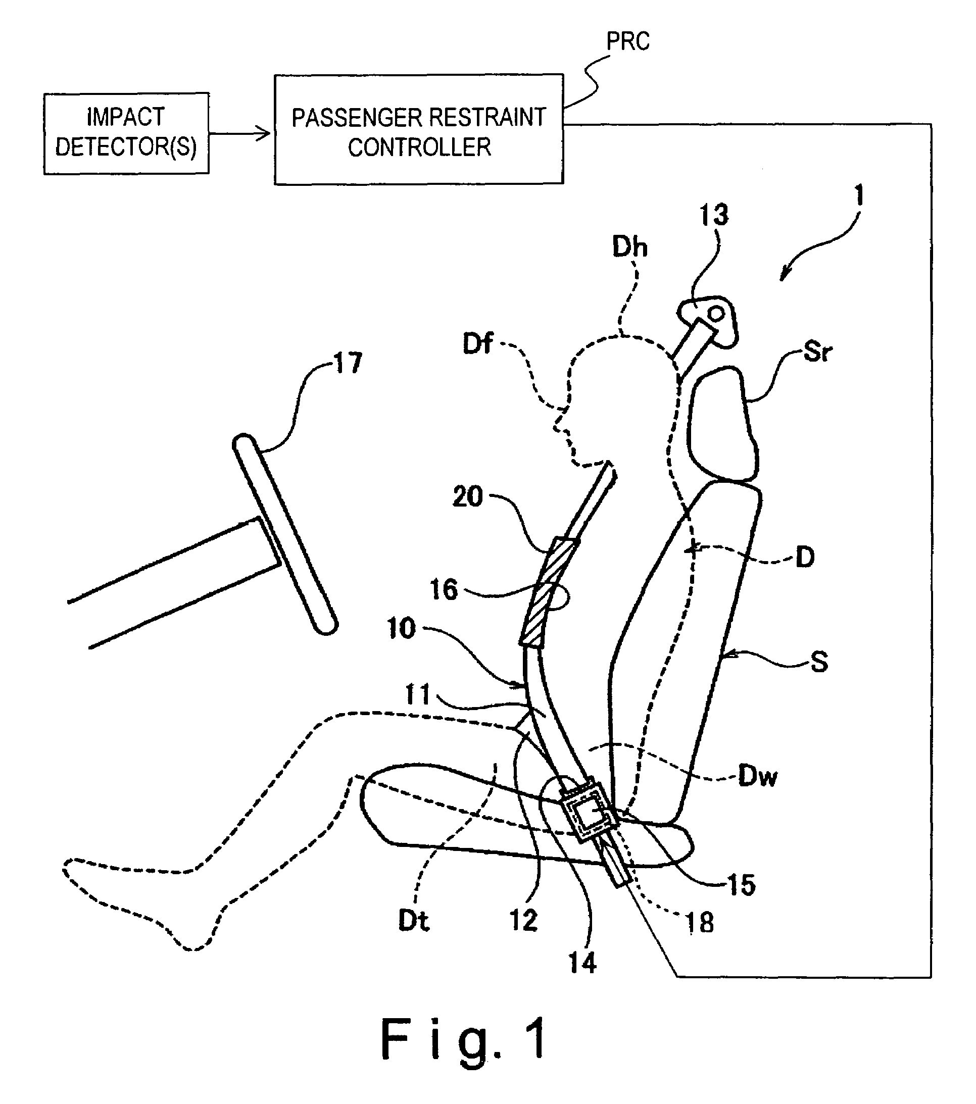
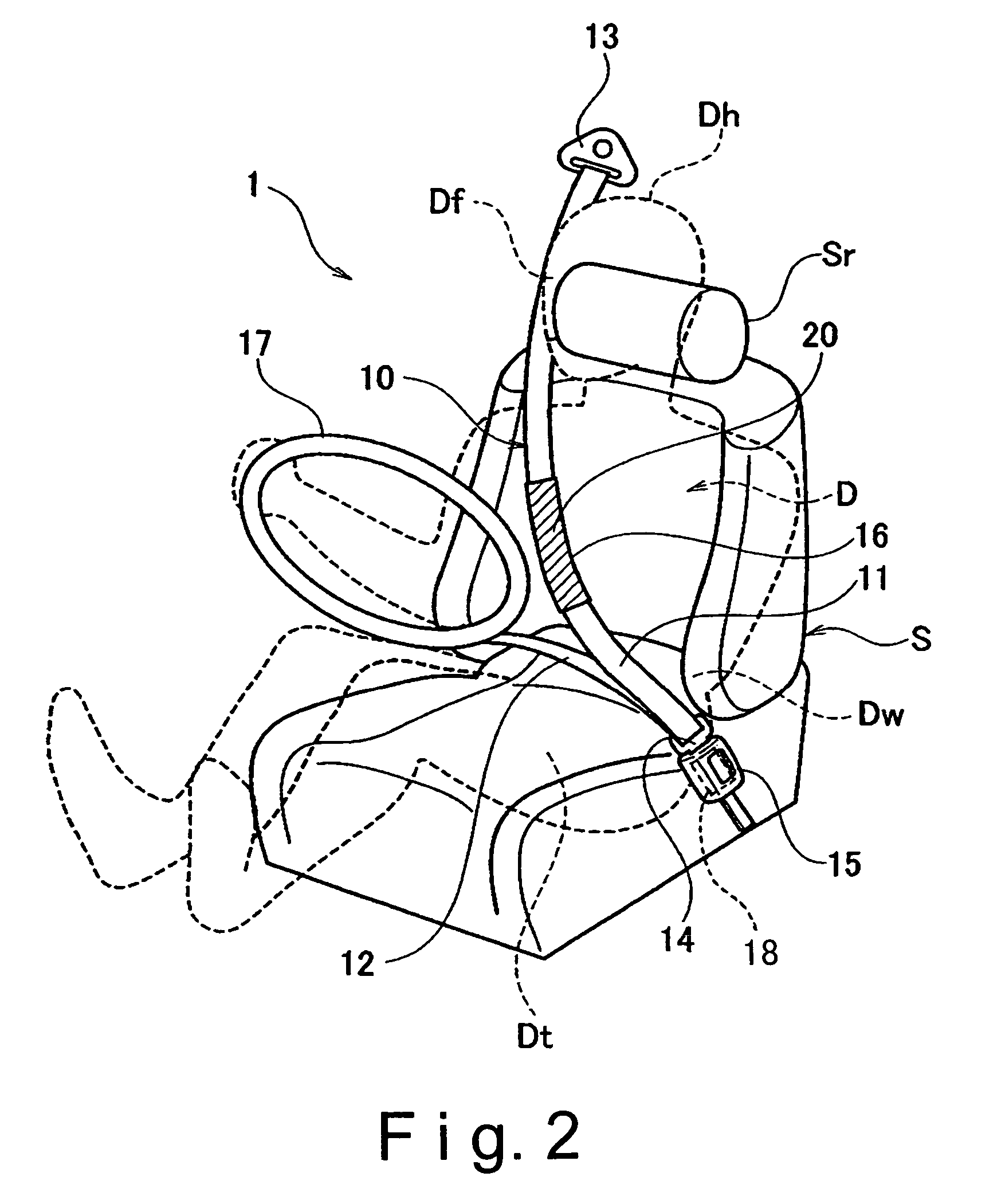
The present invention provides a vehicle passenger restraint system that includes a shoulder belt, a belt inflatable part, and an inflatable head restraining part. The shoulder belt is designed to restrain the passenger to the seat of the vehicle, while the belt inflatable part is connected to the shoulder belt and is designed to inflate with fluid. The head restraining part is connected to the shoulder belt and is designed to expand forward of the passenger to restrain any movement of the passenger's head during a collision. This system eliminates or reduces the need for large frontward airbags, which can be troublesome in terms of design freedom.

Problems solved by technology

Although the conventional vehicle passenger restraint systems as disclosed in the above mentioned reference is configured and arranged to increase the restraining force of the seatbelt with respect to the upper body of the passenger by employing the belt inflatable part, such conventional vehicle passenger restraint system cannot restrain a head portion of the passenger any more than a usual seatbelt can.
These frontward airbags are usually inevitably large to reliably protect the head portion of the passenger when the vehicle undergoes a collision.
Since the frontward airbags are large, they require large storage spaces.
Thus, designing the layout of the storage spaces for these large frontward airbags is troublesome.
In particular, the steering wheel airbag reduces the design freedom of the steering wheel.

Method used


Image

  • Vehicle passenger restraint system
  • Vehicle passenger restraint system
  • Vehicle passenger restraint system

Examples


second embodiment

[0051]Referring now to FIG. 5, a vehicle passenger restraint system 101 in accordance with a second embodiment will now be explained. In view of the similarity between the first and second embodiments, the parts of the second embodiment that are identical to the parts of the first embodiment will be given the same reference numerals as the parts of the first embodiment. Moreover, the descriptions of the parts of the second embodiment that are identical to the parts of the first embodiment may be omitted for the sake of brevity.

[0052]The vehicle passenger restraint system 101 of the second embodiment is basically identical to the vehicle passenger restraint system 1 of the first embodiment except that an additional airbag 120 of the second embodiment is provided with a fluid discharge port 120a configured and arranged to adjust a resistance force (an impact absorbency) of the additional airbag 120.

[0053]FIG. 5 is a frontal perspective view of the vehicle passenger restraint system 10...

third embodiment

[0058]Referring now to FIG. 6, a vehicle passenger restraint system 201 in accordance with a third embodiment will now be explained. In view of the similarity between the first and third embodiments, the parts of the third embodiment that are identical to the parts of the first embodiment will be given the same reference numerals as the parts of the first embodiment. Moreover, the descriptions of the parts of the third embodiment that are identical to the parts of the first embodiment may be omitted for the sake of brevity.

[0059]The vehicle passenger restraint system 201 of the third embodiment differs from the vehicle passenger restraint system 1 of the first embodiment in that the vehicle passenger restraint system 201 of the third embodiment further include a steering wheel airbag 221 (a frontward airbag) that is provided in the steering wheel 17 as well as an additional airbag 220.

[0060]FIG. 6 is a left side elevational view of the vehicle passenger restraint system 201 of the t...

fourth embodiment

[0067]Referring now to FIGS. 7(a), 7(b) and 8, a vehicle passenger restraint system 301 in accordance with a fourth embodiment will now be explained. In view of the similarity between the third and fourth embodiments, the parts of the fourth embodiment that are identical to the parts of the third embodiment will be given the same reference numerals as the parts of the third embodiment. Moreover, the descriptions of the parts of the fourth embodiment that are identical to the parts of the third embodiment may be omitted for the sake of brevity.

[0068]The vehicle passenger restraint system 301 of the fourth embodiment differs from the vehicle passenger restraint system 201 of the third embodiment in that a steering wheel airbag 321 is configured and arranged to deploy only when an impact value indicative of an impact force is detected to be equal to or greater than a threshold value A.

[0069]FIGS. 7 (a) and 7 (b) are left side elevational views of the vehicle passenger restraint system ...


PUM


Abstract

A vehicle passenger restraint system comprises a shoulder belt for restraining a passenger to a vehicle seat. The shoulder belt extends diagonally from a shoulder area on one side of the passenger to a waist area on the opposite side of the passenger and has a belt inflatable part configured to be inflated with a fluid upon a collision of the vehicle is detected. The belt inflatable part is provided with a head restraining part configured to deploy in the forward direction of the vehicle as the belt inflatable part inflates to receive the passenger's head. When the belt inflatable part inflates, tension is generated in the shoulder belt and the tension increases the force with which the passenger is restrained. Simultaneously, the head restraining part is inflated to receive the passenger's head and to prevent the passenger's head from contacting a frontward vehicle part.

Description

CROSS-REFERENCE TO RELATED APPLICATIONS[0001]This application claims priority to Japanese Patent Application No. 2004-120656. The entire disclosure of Japanese Patent Application No. 2004-120656 is hereby incorporated herein by reference.BACKGROUND OF THE INVENTION[0002]1. Field of the Invention[0003]The present invention relates to a vehicle passenger restraint system utilizing a seatbelt with a shoulder belt. More specifically, the present invention relates to a vehicle passenger restraint system with a seatbelt having a belt inflatable part configured and arranged to be inflated upon a detection of an impact imparted to a vehicle.[0004]2. Background Information[0005]Japanese Laid-open Patent Publication No. 2001-294111 discloses a conventional vehicle passenger restraint system employing a seatbelt including a shoulder belt and a lap belt. In this conventional vehicle passenger restraint system, the shoulder belt of the seatbelt includes a belt inflatable part so that a high-pres...

Claims


Application Information

Patent Timeline
Patent Type & Authority Patents(United States)
IPC IPC(8): B60R21/18B60R21/00B60R21/01B60R21/16B60R21/20B60R21/203B60R21/231B60R21/233B60R21/2338B60R21/235
CPCB60R21/18B60R21/231B60R21/203B60R2021/0004B60R2021/23504B60R2021/0048B60R2021/01034B60R2021/23107B60R2021/23382B60R2021/0009
Inventor WATANABE, YOICHI
Owner NISSAN MOTOR CO LTD
Learn More