

Light-transmitting conductive laminate and light-transmitting conductive molded body using same
a technology of conductive laminate and molded body, which is applied in the direction of instruments, other domestic objects, synthetic resin layered products, etc., can solve the problems of reducing design freedom, affecting the appearance of the surface, and the driver cannot recognize where the driver is touching, so as to achieve high design freedom
Active Publication Date: 2019-03-07
TORAY IND INC
View PDF9 Cites 3 Cited by
- Summary
- Abstract
- Description
- Claims
- Application Information
AI Technical Summary
Benefits of technology
The present invention provides a light-transmitting conductive laminate that can be molded into a shape allowing easy operation without sacrificing the good design. The laminate can be used, for example, as a touch switch in a car, providing a high design freedom and allowing the driver to recognize where the driver is touching. Additionally, the laminate can be provided with surface irregularity that can be recognized by touching, and therefore, the presence of the switch can be recognized while the driver is looking forward during the driving and the switch functions without erroneous operation.
Problems solved by technology
However, current liquid crystal display is a flat plane, and this results in the reduced design freedom in the case of the car interior where the articles often have three dimensional shape.
There has also been a problem that the driver could not recognize where the driver is touching because the touch sensor provided on the liquid crystal display was also a flat plane.
With regard to the appearance and feel of the surface, the synthetic leather produced by coating a resin on a woven fabric and giving a full grain leather-like texture to the surface and the artificial leather produced by impregnating a polymeric elastomer in a nonwoven fabric and giving a full grain leather-like texture or suede-like texture to the surface both suffered from lack of high-quality appearance.
However, the switch is turned on by pushing the leather-like sheet and the leather-like sheet is deformed by the pushing, and as a consequence, the favorable appearance was lost by the repeated operation due to the stretching of the leather-like sheet and the friction applied to the leather-like sheet in the course of the strong pushing.
Method used
View moreImage
Smart ImageViewing Examples

Examples
example 1
[0122]A thermoplastic polyurethane hot melt adhesive (softening point, 100° C.) in molten state was placed on the back surface of the surface material 1 in dots, and the transparent conductive substrate 1 was disposed with the intervening adhesive coating layer, and these layers were adhered by passing between a metal roll and a back roll maintained at a surface temperature 130° C. to thereby produce a light-transmitting conductive laminate 1.
example 2
[0123]The procedure of Example 1 was repeated except for the use of the surface material 2 to produce a light-transmitting conductive laminate 2.
example 3
[0124]The procedure of Example 1 was repeated except for the use of the surface material 3 to produce a light-transmitting conductive laminate 3.
Login to View More PUM
| Property | Measurement | Unit |
|---|---|---|
| brightness | aaaaa | aaaaa |
| brightness | aaaaa | aaaaa |
| apparent density | aaaaa | aaaaa |
Abstract
Provided is a light-transmitting conducive laminate which is moldable and has good designability. A light-transmitting conductive laminate is provided in which at least a surface skin material and a transparent conductive base are sequentially laminated from the input side.
Description
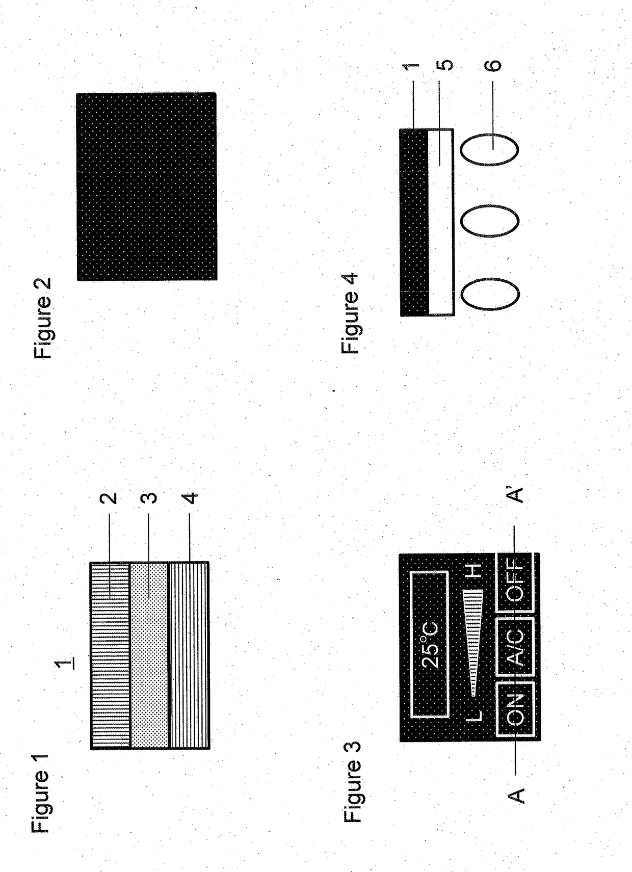
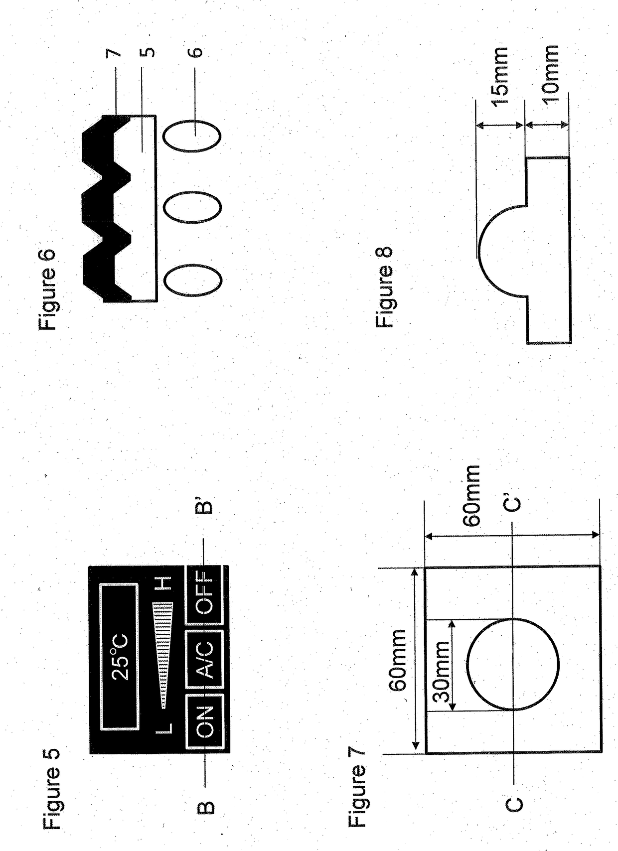
CROSS REFERENCE TO RELATED APPLICATIONS[0001]This is the U.S. National Phase application of PCT / JP2017 / 009003, filed Mar. 7, 2017, which claims priority to Japanese Patent Application No. 2016-047994, filed Mar. 11, 2016, the disclosures of these applications being incorporated herein by reference in their entireties for all purposes.FIELD OF THE INVENTION[0002]The present invention relates to a light-transmitting conductive laminate. More specifically, the present invention relates to a light-transmitting conductive laminate which allows light transmission as well as three dimensional molding and which has excellent electro-conductivity; and also, to a light-transmitting conductive molded laminate produced by using such light-transmitting conductive laminate.BACKGROUND OF THE INVENTION[0003]Mechanical switches have been provided near the driver's seat of cars to control audio and equipment heater control panel. Although mechanical switches have the merits of less frequent malfuncti...
Claims
Login to View More Application Information
Patent Timeline
 Patent Type & AuthorityApplications(United States)
IPC IPC(8): G06F3/044B32B7/02D06N3/00B32B27/12B60K35/00
CPCG06F3/044B32B7/02D06N3/0011B32B27/12B60K35/00B60K2350/1036B32B2307/202G06F2203/04809D06N3/00G06F3/041B32B5/022B32B5/024B32B9/025B32B15/20B32B25/00B32B25/02B32B15/06B32B15/14B32B15/04B32B2250/02B32B2260/021B32B2260/048B32B2262/02B32B2307/412B32B2457/00B32B2457/208B32B2262/106B32B2264/108B60K35/10B60K2360/1446B32B7/12B32B9/045B32B27/20B32B27/36
InventorNAKAI, SHUNICHIROTSUKAMOTO, AKIHITOTSUJIUCHI, NAOKIIWANAGA, KEJI
OwnerTORAY IND INC