Scroll-type fluid machine
a fluid machine and roller technology, applied in the direction of machines/engines, rotary/oscillating piston pump components, liquid fuel engines, etc., can solve the problems of increased sliding loss, difficult to control the size, increased sliding loss, etc., to prevent the damage caused by excessive load on the annular u sealing member, reduce the installation space of the sealing member, and improve durability
- Summary
- Abstract
- Description
- Claims
- Application Information
AI Technical Summary
Benefits of technology
Problems solved by technology
Method used
Image
Examples
first embodiment
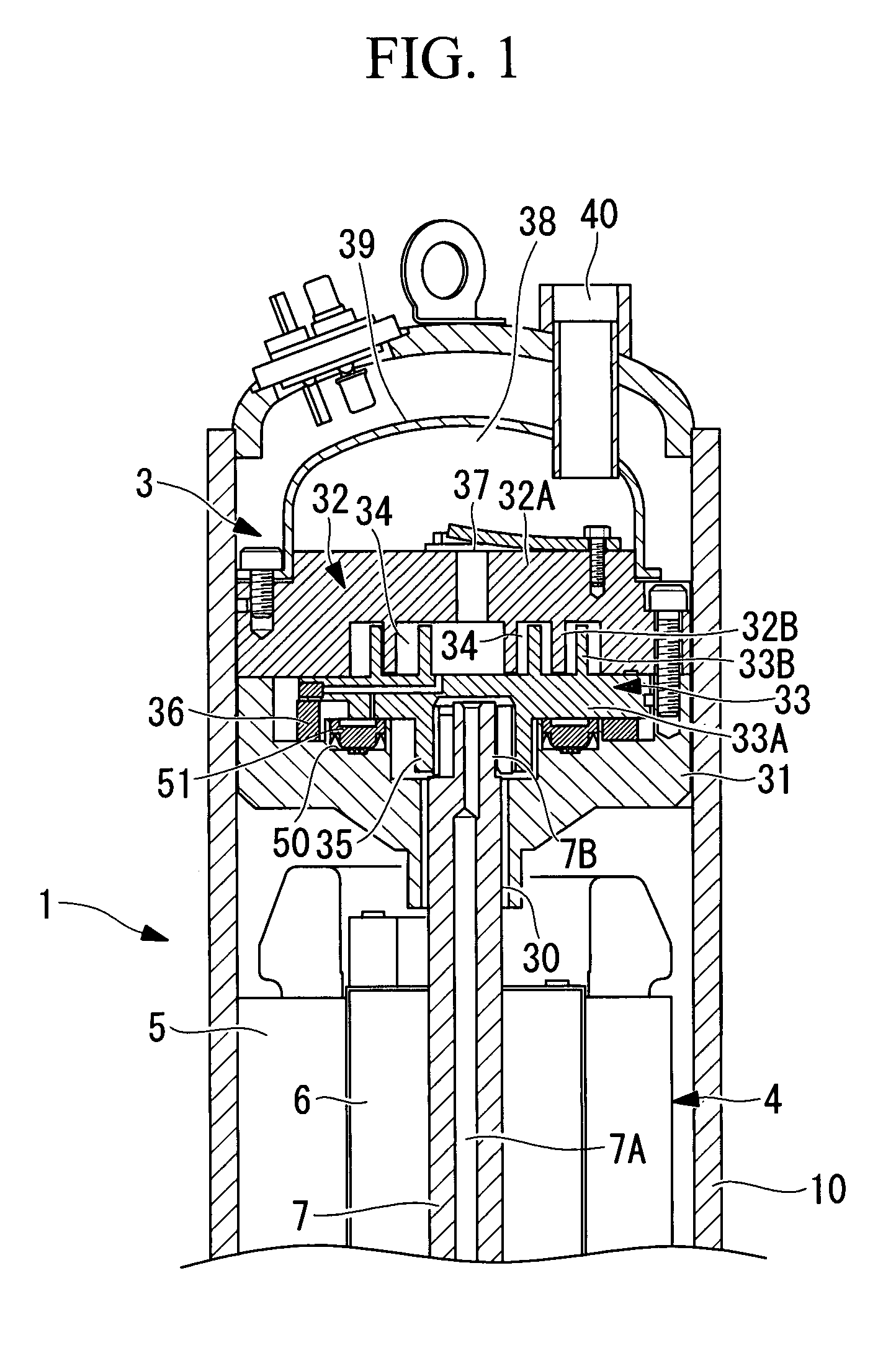
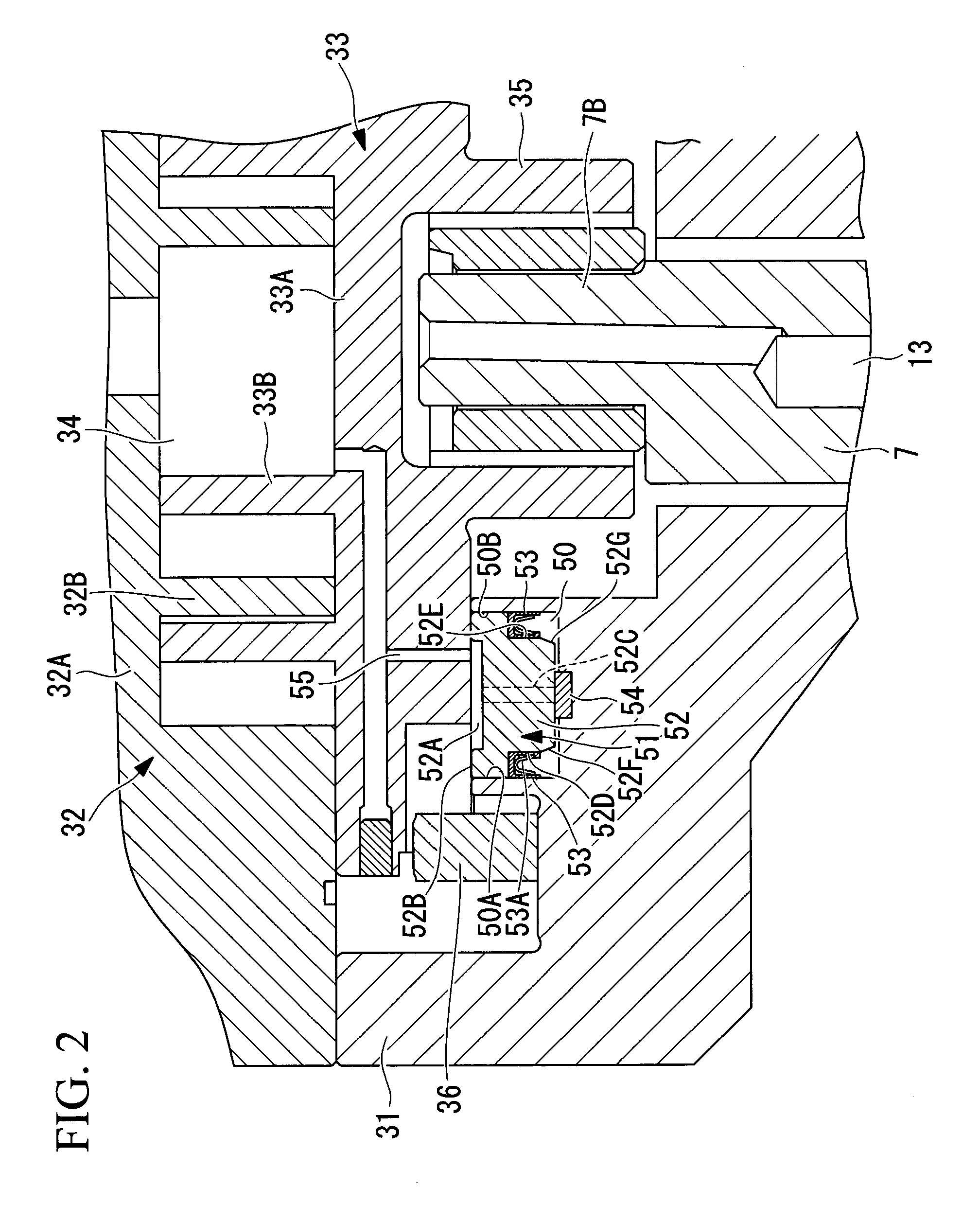
[0051]A first embodiment of the present invention will be described below with reference to FIGS. 1 and 2.
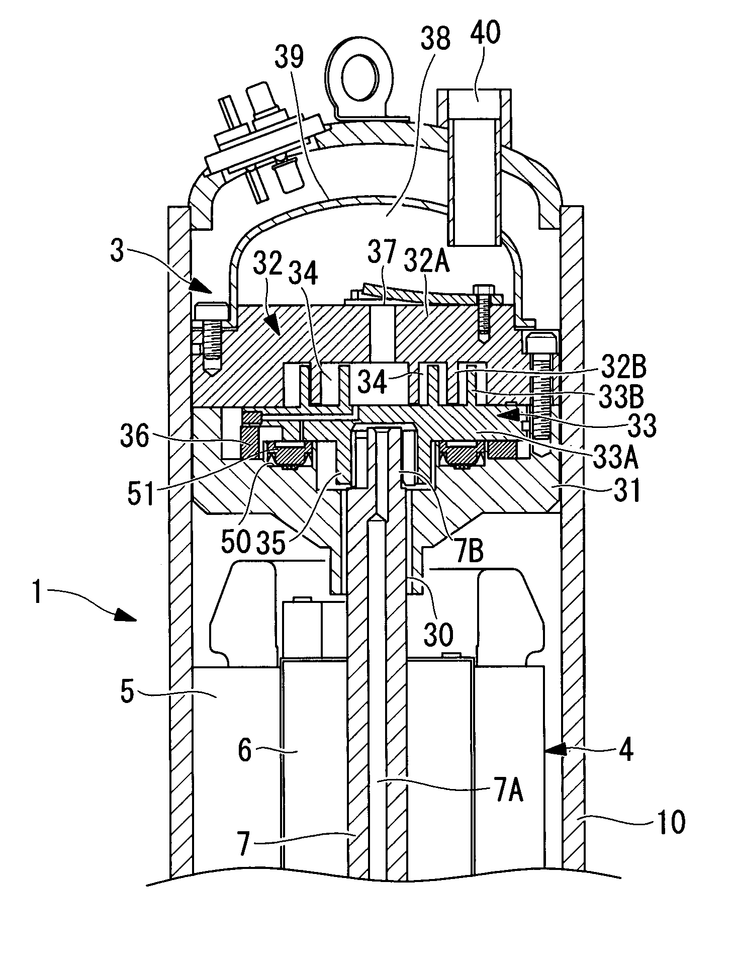
[0052]FIG. 1 is a longitudinal sectional view of a scroll compressor 1, which is an example of a scroll-type fluid machine. In this embodiment, for convenience, the scroll compressor 1 for refrigerant compression will be described. However, the present invention is not limited to this scroll compressor 1 for refrigerant compression.
[0053]The scroll compressor 1 includes a sealed housing 10. An electric motor 4 constructed of a stator 5 and a rotor 6 is securely mounted at the lower section inside the sealed housing 10, and a scroll compressing mechanism 3 is securely mounted at the upper section. A crank shaft 7 is integrated with the rotor 6. A feeding hole 7A is formed at the shaft center in the axial direction of the crank shaft 7 so as to enable force feeding of a lubricant contained in the bottom section of the sealed housing 10 through the feeding hole 7 with a feeding pum...
second embodiment
[0067]Next, a second embodiment of the present invention will be described with reference to FIG. 3.
[0068]This embodiment differs from the above-described first embodiment in the configuration of an annular back-pressure chamber 60 and a sealing member 61. Since other aspects are the same as those in the first embodiment, descriptions thereof are omitted.
[0069]In this embodiment, the sealing member 61 is disposed on the inward side of a rotation prevention mechanism 36 on a thrust supporting surface of a fixed support member 31, and the entire area on the inward side comprises the back-pressure chamber 60. In such a case, a shoulder section 60A for mounting the sealing member 61 is provided on the inner circumference of a depression accommodating a boss section 35 of a fixed support member 31, and an annular plate member 62 and an annular U sealing member 53 constituting the sealing member 61 are mounted on this shoulder section 60A.
[0070]Similar to the first embodiment, the annular...
third embodiment
[0073]Next, a third embodiment of the present invention will be described with reference to FIG. 4.
[0074]This embodiment differs from the above-described second embodiment in the configuration of a sliding surface 72A of an annular plate member 62. Since other aspects are the same as those in the first and second embodiments, descriptions thereof are omitted.
[0075]In this embodiment, a width W1 of the sliding surface 72A of the annular plate member 62 on which the back side of a revolving scroll member 33 slides is substantially equal to a width W2 of a annular U sealing member 53.
[0076]As described above, by setting the width W1 of the sliding surface 72A of the annular plate member 62 substantially equal to the width W2 of the annular U sealing member 53, the width W1 of the sliding surface 72A can be reduced compared to that matched to the side surface length of the annular U sealing member 53. Therefore, the area of the sliding surface 72A of the annular plate member 62 can be r...
PUM
 Abstract
Description
Claims
Application Information
 - R&D
- Intellectual Property
- Life Sciences
- Materials
- Tech Scout
- Unparalleled Data Quality
- Higher Quality Content
- 60% Fewer Hallucinations
Browse by: Latest US Patents, China's latest patents, Technical Efficacy Thesaurus, Application Domain, Technology Topic, Popular Technical Reports.
© 2025 PatSnap. All rights reserved.Legal|Privacy policy|Modern Slavery Act Transparency Statement|Sitemap|About US| Contact US: help@patsnap.com


