Scroll-type fluid machine having a back-pressure chamber

a fluid machine and back-pressure chamber technology, applied in the direction of machines/engines, rotary/oscillating piston pump components, liquid fuel engines, etc., can solve the problems of increased sliding loss, difficult to control the size, increased sliding loss, etc., to prevent the damage caused by excessive load on the annular u sealing member, reduce the installation space of the sealing member, and improve durability

Active Publication Date: 2011-10-04
MITSUBISHI HEAVY IND LTD
View PDF12 Cites 3 Cited by
  • Summary
  • Abstract
  • Description
  • Claims
  • Application Information

AI Technical Summary

Benefits of technology

[0009]However, usually, a pre-load spring is provided inside a U sealing member so as to pull both edges of an opening outward. Therefore, when the U sealing member is used as the sealing member of a back-pressure chamber, it is difficult to control the size, including a sliding surface, in the height direction, and uneven pre-load forces are applied to the revolving scroll member by pushing the sliding surface, thus causing the sliding loss to increase. The annular U sealing member is laterally installed such that its side surface is parallel to the sliding direction of the revolving scroll member; therefore, there are problems in that the sliding surface area of the sealing member increases, the sliding loss increases, the installation space in the sliding direction of the sealing member, i.e., the installation space in the radial direction of the scroll member, increases, and thus the design freedom is reduced.

Problems solved by technology

Therefore, when the U sealing member is used as the sealing member of a back-pressure chamber, it is difficult to control the size, including a sliding surface, in the height direction, and uneven pre-load forces are applied to the revolving scroll member by pushing the sliding surface, thus causing the sliding loss to increase.
The annular U sealing member is laterally installed such that its side surface is parallel to the sliding direction of the revolving scroll member; therefore, there are problems in that the sliding surface area of the sealing member increases, the sliding loss increases, the installation space in the sliding direction of the sealing member, i.e., the installation space in the radial direction of the scroll member, increases, and thus the design freedom is reduced.
Thus, it is a significant problem to ensure a sufficient installation space for the sealing member forming the back-pressure chamber in a support surface space on the fixed support member side, where a thrust bearing surface supporting the back side of the revolving scroll member and a rotation prevention mechanism are provided.

Method used


Image

  • Scroll-type fluid machine having a back-pressure chamber
  • Scroll-type fluid machine having a back-pressure chamber
  • Scroll-type fluid machine having a back-pressure chamber

Examples


first embodiment

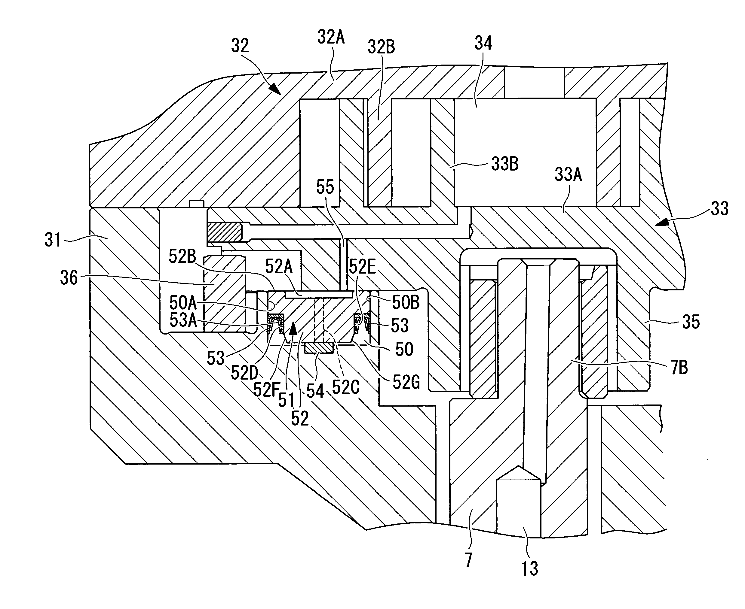
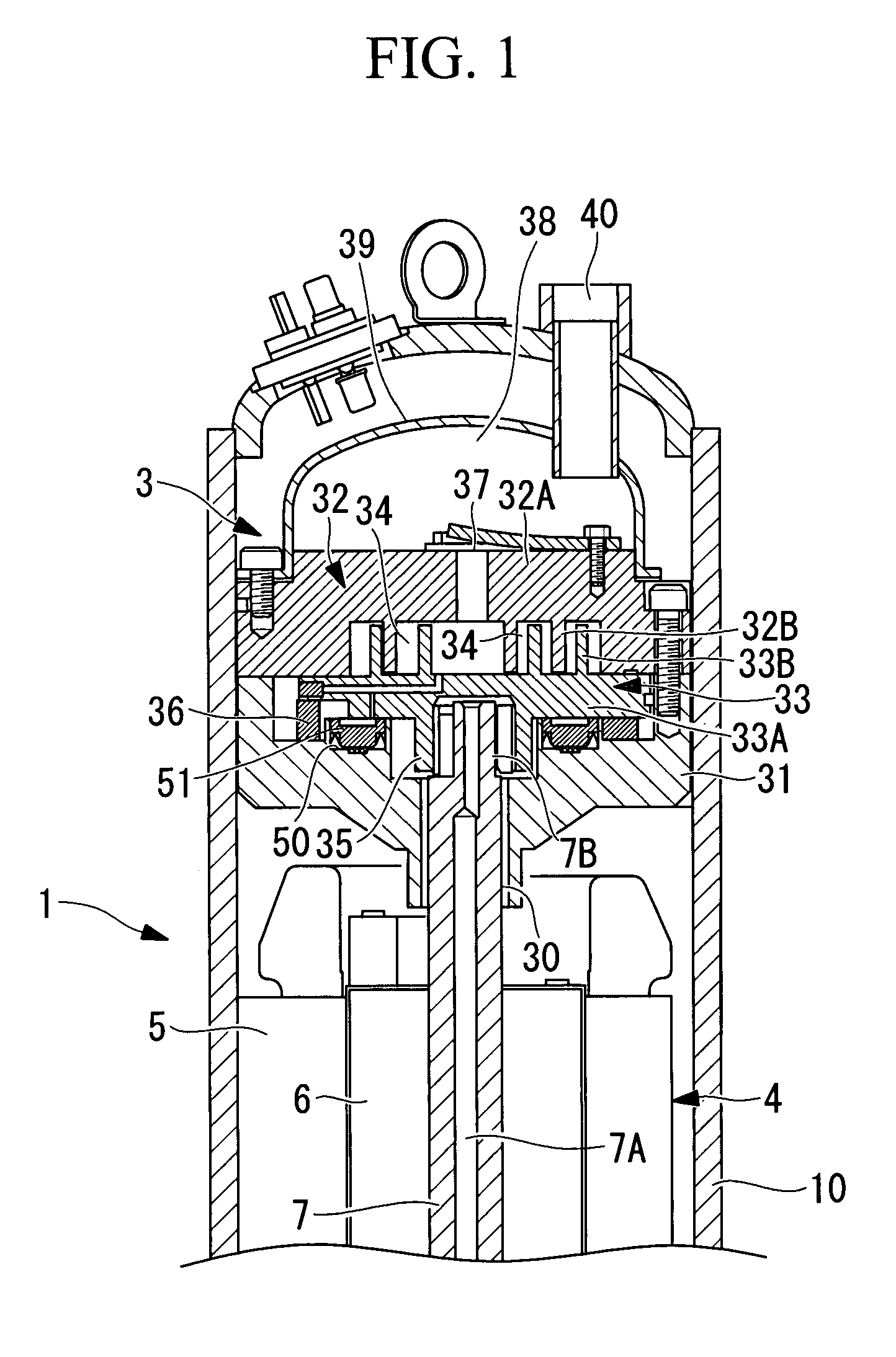
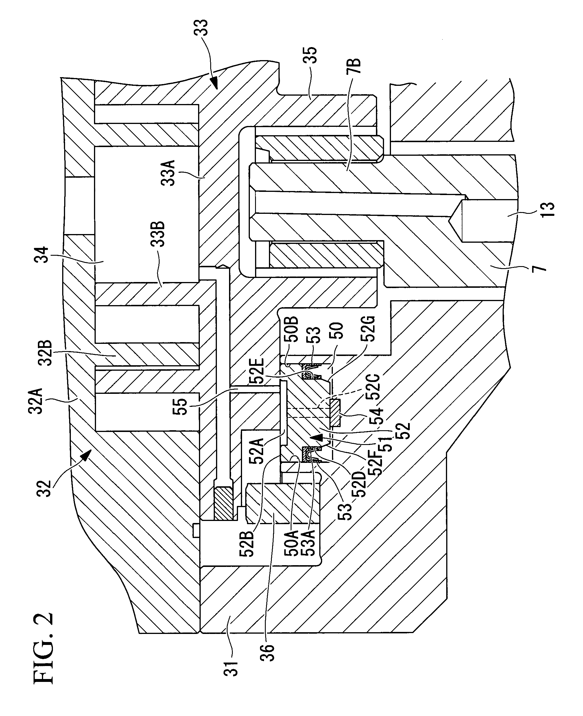
[0051]A first embodiment of the present invention will be described below with reference to FIGS. 1 and 2.

[0052]FIG. 1 is a longitudinal sectional view of a scroll compressor 1, which is an example of a scroll-type fluid machine. In this embodiment, for convenience, the scroll compressor 1 for refrigerant compression will be described. However, the present invention is not limited to this scroll compressor 1 for refrigerant compression.

[0053]The scroll compressor 1 includes a sealed housing 10. An electric motor 4 constructed of a stator 5 and a rotor 6 is securely mounted at the lower section inside the sealed housing 10, and a scroll compressing mechanism 3 is securely mounted at the upper section. A crank shaft 7 is integrated with the rotor 6. A feeding hole 7A is formed at the shaft center in the axial direction of the crank shaft 7 so as to enable force feeding of a lubricant contained in the bottom section of the sealed housing 10 through the feeding hole 7 with a feeding pum...

second embodiment

[0067]Next, a second embodiment of the present invention will be described with reference to FIG. 3.

[0068]This embodiment differs from the above-described first embodiment in the configuration of an annular back-pressure chamber 60 and a sealing member 61. Since other aspects are the same as those in the first embodiment, descriptions thereof are omitted.

[0069]In this embodiment, the sealing member 61 is disposed on the inward side of a rotation prevention mechanism 36 on a thrust supporting surface of a fixed support member 31, and the entire area on the inward side comprises the back-pressure chamber 60. In such a case, a shoulder section 60A for mounting the sealing member 61 is provided on the inner circumference of a depression accommodating a boss section 35 of a fixed support member 31, and an annular plate member 62 and an annular U sealing member 53 constituting the sealing member 61 are mounted on this shoulder section 60A.

[0070]Similar to the first embodiment, the annular...

third embodiment

[0073]Next, a third embodiment of the present invention will be described with reference to FIG. 4.

[0074]This embodiment differs from the above-described second embodiment in the configuration of a sliding surface 72A of an annular plate member 62. Since other aspects are the same as those in the first and second embodiments, descriptions thereof are omitted.

[0075]In this embodiment, a width W1 of the sliding surface 72A of the annular plate member 62 on which the back side of a revolving scroll member 33 slides is substantially equal to a width W2 of a annular U sealing member 53.

[0076]As described above, by setting the width W1 of the sliding surface 72A of the annular plate member 62 substantially equal to the width W2 of the annular U sealing member 53, the width W1 of the sliding surface 72A can be reduced compared to that matched to the side surface length of the annular U sealing member 53. Therefore, the area of the sliding surface 72A of the annular plate member 62 can be r...


PUM


Abstract

Provided is scroll-type fluid machine that facilitates the formation of a back-pressure chamber so as to increase the design freedom in the space on the back side of the revolving scroll member, where it is difficult to ensure sufficient space, by decreasing, as much as possible, the installation space of the sealing member partitioning the back-pressure chamber. In the scroll-type fluid machine, a back-pressure chamber to which high-pressure gas is introduced is partitioned between the revolving scroll member and a fixed support member, a sealing member is constructed of an annular U sealing member, the annular U sealing member is oriented in a direction orthogonal to the back side of the revolving scroll member, and one side contacts a side surface (sealed surface) of a fixed support member.

Description

TECHNICAL FIELD[0001]The present invention relates to a scroll-type fluid machine having a partitioned configuration in which a back-pressure chamber to which high-pressure gas is introduced is formed at the back side of a revolving scroll member.BACKGROUND ART[0002]The scroll-type fluid machine forms a working gas chamber by combined paired fixed scroll member and revolving scroll member, which are formed by vertically mounting spiral wraps on end plates, with their phases shifted. With such a scroll-type fluid machine, the gas pressure in the working gas chamber acts in a direction to separate the fixed scroll member and the revolving scroll member. In this way, the distance between the tips of the spiral wraps increases, causing gas leakage. As a countermeasure, a back-pressure chamber in which high-pressure gas is introduced is partitioned at the back side of the revolving scroll member, and the revolving scroll member is pushed toward the fixed scroll member by the gas pressure...

Claims


Application Information

Patent Timeline
Patent Type & Authority Patents(United States)
IPC IPC(8): F03C2/00F04C2/00F03C4/00
CPCF04C18/0215F04C27/005F04C23/008
Inventor SATO, HAJIMEKIMATA, YOSHIYUKI
Owner MITSUBISHI HEAVY IND LTD
Why Eureka
Try Eureka