Supercharge Your Innovation With Domain-Expert AI Agents!

System and method for interrogating and locating a transponder relative to a zone-of-interest

a transponder and zone technology, applied in waveguide horns, instruments, reradiation, etc., can solve the problems of bulky and difficult transportation of conventional battlefield communication systems

Active Publication Date: 2009-08-11
ATR ELECTRONICS INC +1
View PDF13 Cites 16 Cited by
  • Summary
  • Abstract
  • Description
  • Claims
  • Application Information

AI Technical Summary

Benefits of technology

The system enables efficient, directional communication and warning, reducing the risk of fratricide by providing a compact, lightweight, and energy-efficient solution compatible with various weapons and platforms, enhancing mobility and secure communication.

Problems solved by technology

However, conventional battlefield communication systems are bulky and thus difficult to transport.

Method used


Image

  • System and method for interrogating and locating a transponder relative to a zone-of-interest
  • System and method for interrogating and locating a transponder relative to a zone-of-interest
  • System and method for interrogating and locating a transponder relative to a zone-of-interest

Examples


Embodiment Construction

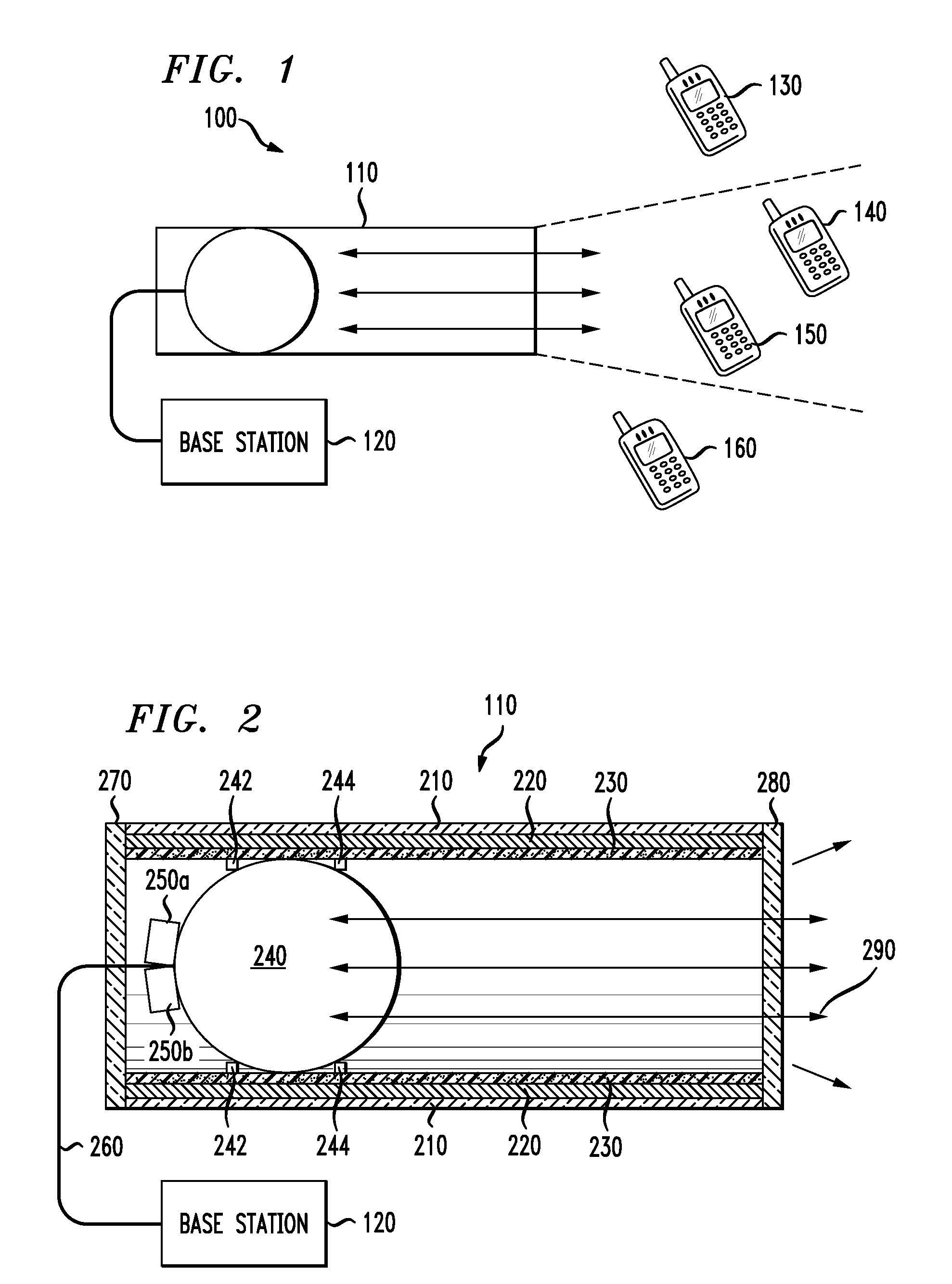
[0018]Referring initially to FIG. 1, illustrated is a schematic view of one embodiment of a directional communication system constructed according to the principles of the invention and configured to operate as a directional warning system. The directional communication system, generally designated 100, includes a directional antenna 110 and a base station 120. The directional antenna 110 is a directional antenna that transmits signals that travel out as a beam within a defined cone. The directional antenna 110 also receives signals that originate within the defined cone. The structure and function of the directional antenna 110 will be set forth in substantially greater detail in conjunction with FIG. 2.

[0019]The base station 120 may be analog or digital, capable of transmitting or receiving on any operating frequency or band of frequencies suitable to a Luneberg lens and capable of transmitting at any suitable power level. Those skilled in the pertinent art will understand that a ...


PUM


Abstract

A directional warning system and a method of warning of friendly forces. In one embodiment, the system includes: (1) a conductive shield having an opening at an end thereof and a radio frequency absorptive material located on an inner surface thereof, (2) a Luneberg lens located within the conductive shield and (3) a plurality of feed horns located proximate a portion of the Luneberg lens that is distal from the opening and arranged relative thereto based on a zone-of-interest with which the directional warning system may be associated.

Description

CROSS-REFERENCE TO RELATED APPLICATION[0001]The present application is related to and claims priority based on U.S. Provisional Application Ser. No. 60 / 714,930, filed by Hayles, et al., on Sep. 7, 2005, entitled “A Compact Portable Interrogation and Response System,” commonly assigned with the invention and incorporated herein by reference. The present application is also related to U.S. patent application Ser. No. 10 / 972,958, filed by Hayles, et al., on Oct. 25, 2004, entitled “System and Method for Highly Directional Electronic Identification and Communication and Combat Identification System Employing the Same,” incorporated herein by reference.TECHNICAL FIELD OF THE INVENTION[0002]The invention is directed, in general, to wireless identification and communication systems and, more particularly, to a system and method for interrogating and locating a transponder relative to a zone-of-interest which, in the context of a weapon, is called a “kill zone.”BACKGROUND OF THE INVENTION[0...

Claims


Application Information

Patent Timeline
Patent Type & Authority Patents(United States)
IPC IPC(8): H04Q5/22
CPCG01S13/78H01Q19/062H01Q13/02H01Q1/3233
Inventor HAYLES, JR., RALPH E.MORYL, JAMES A.
Owner ATR ELECTRONICS INC
Features
  • R&D
  • Intellectual Property
  • Life Sciences
  • Materials
  • Tech Scout
  • Unparalleled Data Quality
  • Higher Quality Content
  • 60% Fewer Hallucinations
Learn More